dVRK controller compatible foot pedals
The goal of this section is to show how to build some dVRK compatible foot pedals. These can only be used with the dVRK controllers and can’t be connected directly to a PC. This can be useful if you’re splitting your dVRK into two systems (e.g., one MTM/PSM on one controller and the other MTM/PSM on another controller) or if you use a spare PSM with an alternate master arm (e.g., PSM and Force Dimension master).
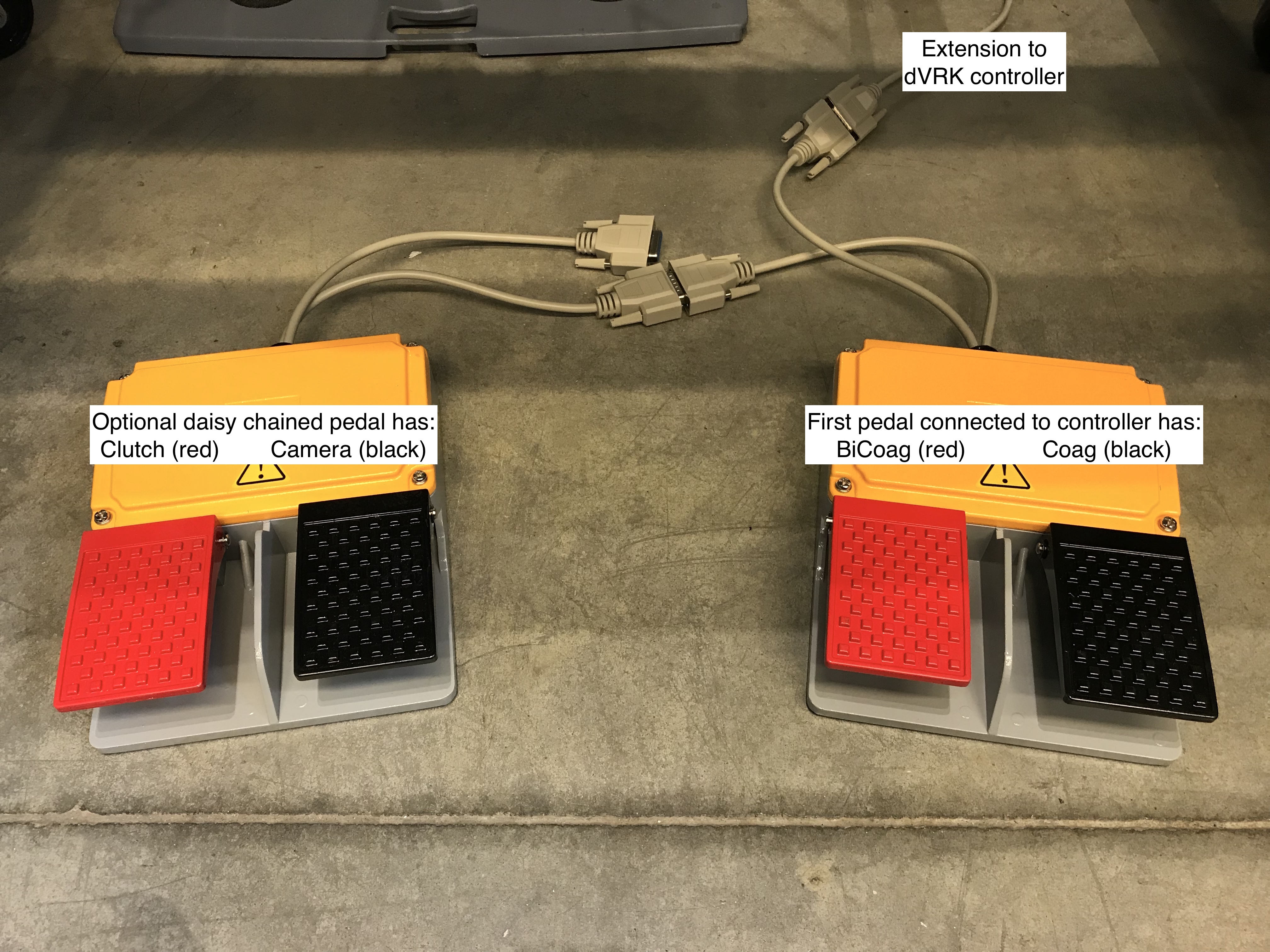
The design described below is based on up to 3 pairs of foot pedals. One can use one, two or three pairs as needed. The wiring allows to swap the pedals without any software reconfiguration. This configuration is also pin compatible with the real da Vinci foot pedals. By default, the first pair of foot pedals is wired as the right two pedals on the da Vinci (from left to right: bi-coag and coag) and the second pair of pedals is wired as the left two pedals (from left to right: clutch and camera):
Material
One (or two or three) pairs of foot pedals. We found that these pedals are nicely built and heavy enough to not slide on the floor when used: https://smile.amazon.com/dp/B077NM69DL The following model might work as well but we didn’t try: https://smile.amazon.com/Plastic-Double-Action-Switch-Pedal/dp/B077NK8XYZ
Cables: https://smile.amazon.com/Monoprice-6ft-DB15-Molded-Cable/dp/B002LWJ7TA You will need 2 to 4 cables.
Wiring
To minimize the amount of soldering we simply cut one DB 15 extension cable in two (one cable per foot pedal). The wiring for two foot pedals (i.e., without the optional 3rd foot pedal for camera +/-) can be seen in the following picture (credit: Christian Hernandez):
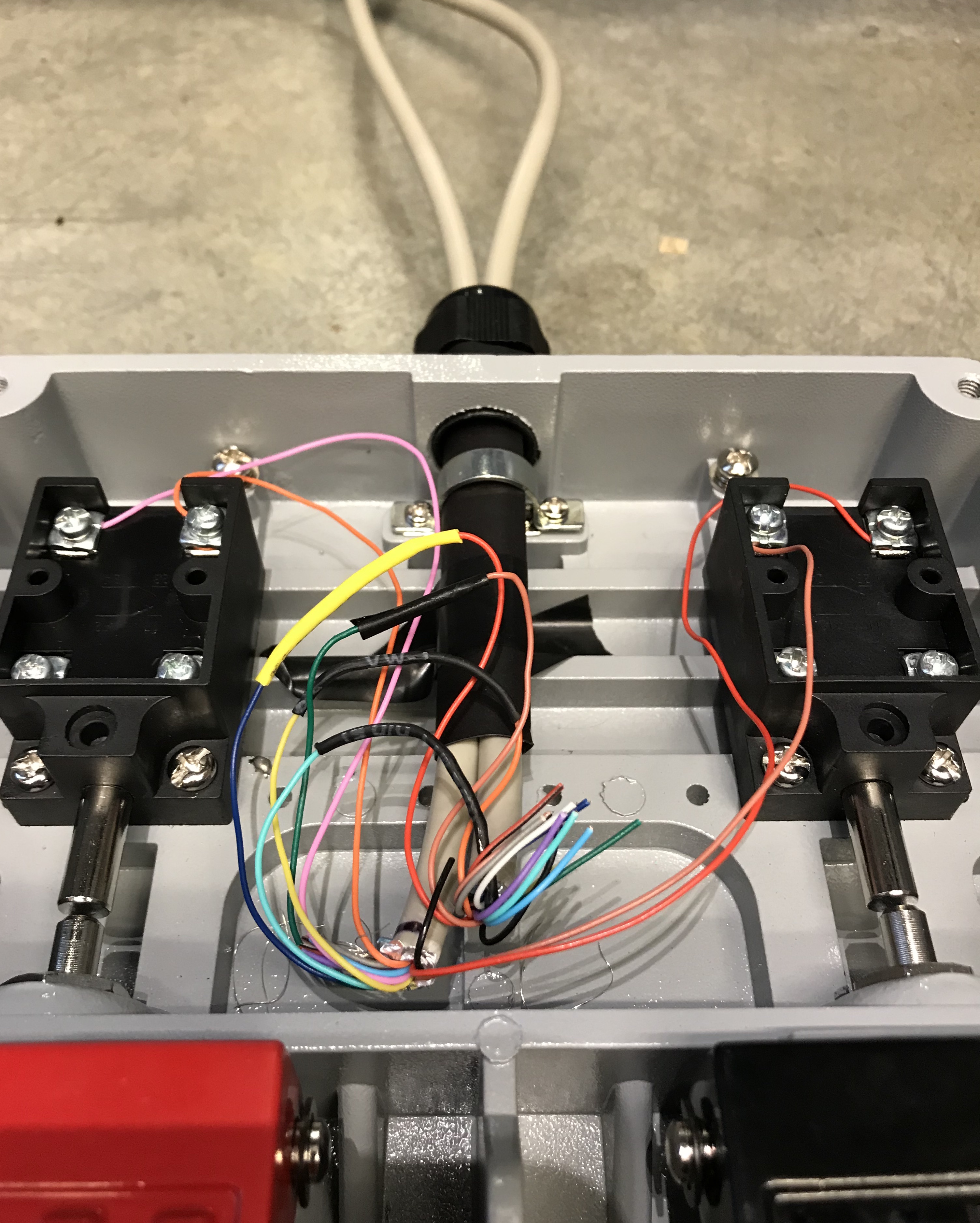
da Vinci compatible foot pedals, internal wiring
The complete wiring can be found in this PDF file or in
Altium Designer format.
Configuration
To configure your console, see foot pedals configuration.