da Vinci Head Sensor
Wiring
The head sensor is located under the master console’s cover. It has four strobing LEDs on one side and four light sensors on the other side. It is mounted on the head’s sides, behind the 4 round holes forming a diamond shape on each side.
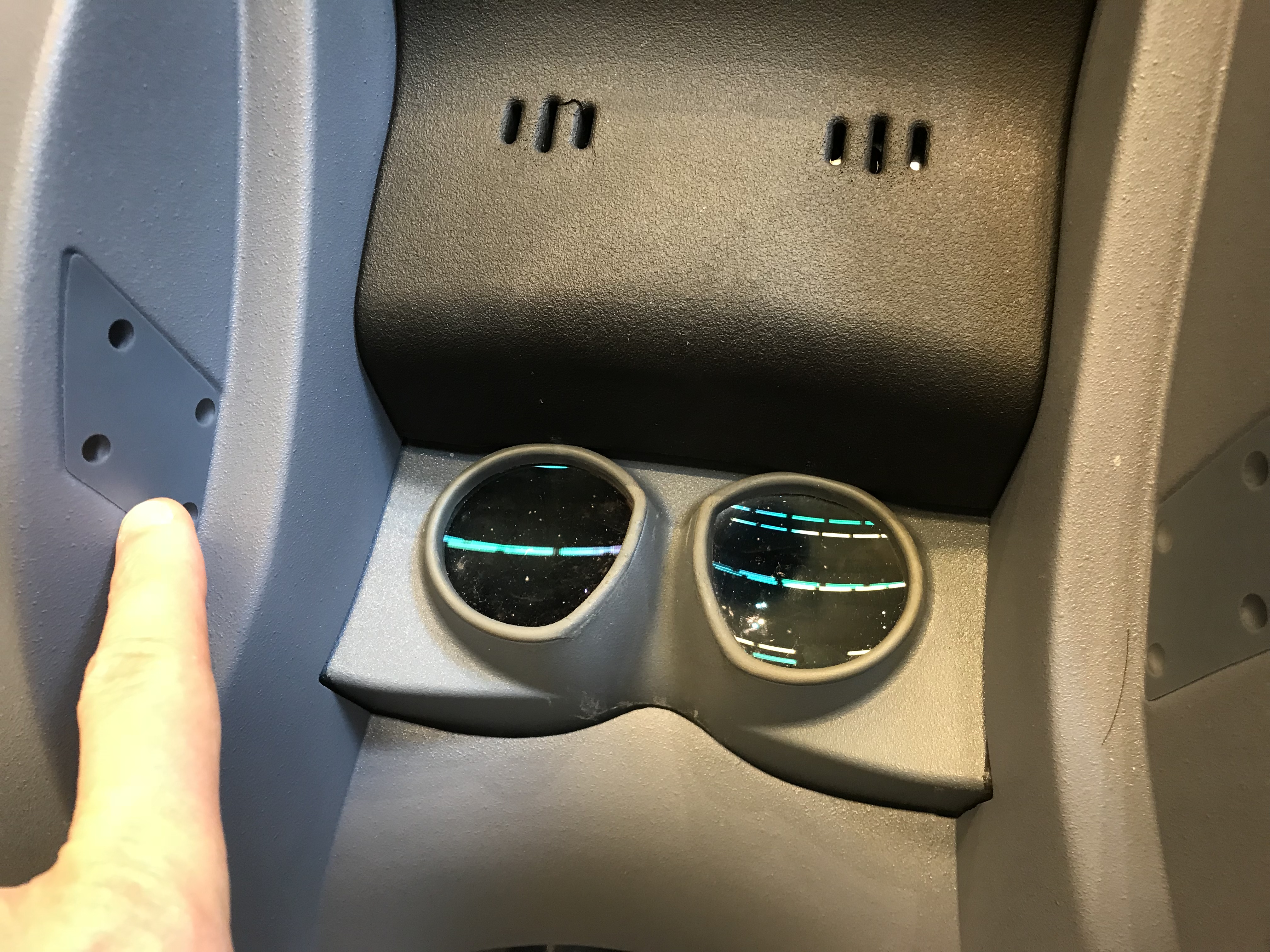
da Vinci Classic head sensor
Under the cover, there’s a long cable going to the ISI controller at the base of the master console. There’s also a short cable going between the LEDs on one side and the sensors on the other side. The sensors are hidden behind a metal plate to make sure only the lights from the LEDs can be detected. It is recommended to leave these alone!
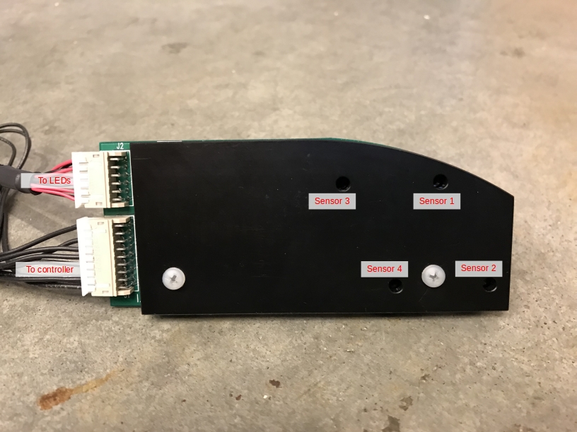
da Vinci Classic head sensor (internals)
We found that the easiest solution to connect to the head sensor is to locate the DB 25 cable that connects both the head sensor and the speakers under the surgeon’s console. That connector is located on the back of the console, on the left side, just behind the arms. You will need to take the side cover off to find it:
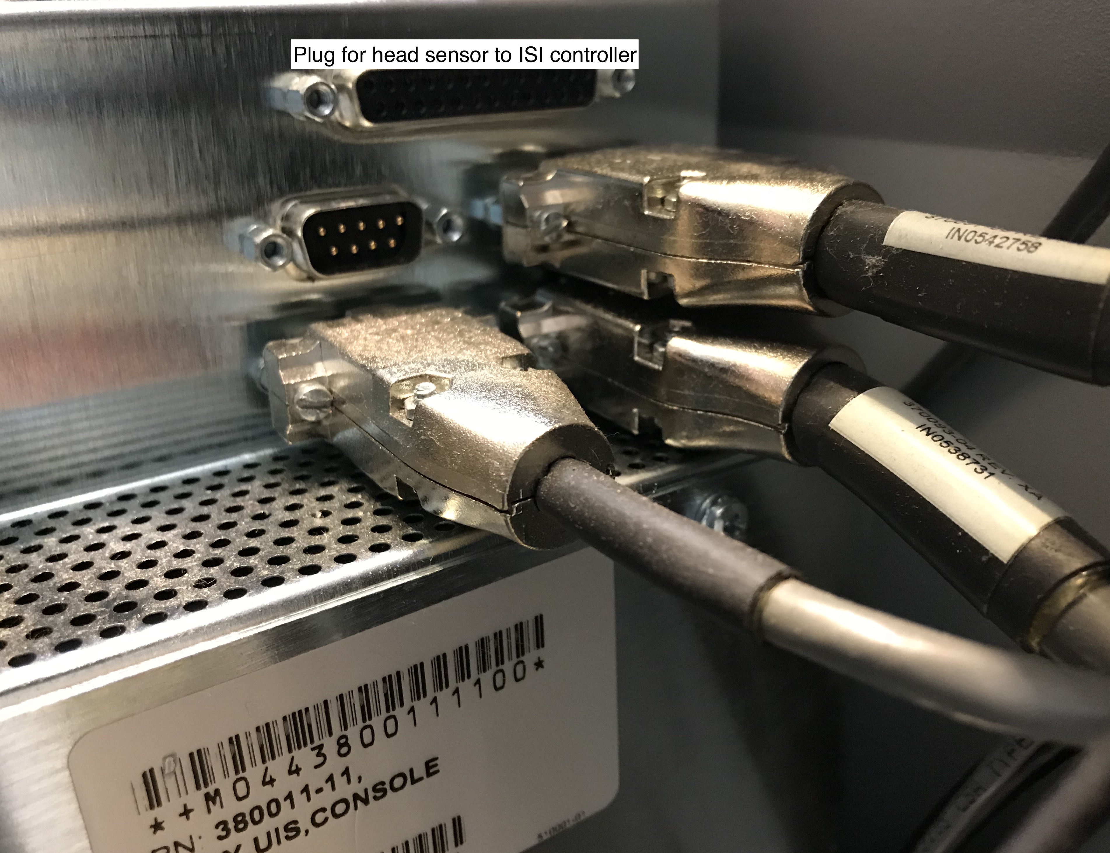
da Vinci Classic head sensor connector
You will then need to make a new cable to connect the da Vinci head sensor to the dVRK controllers. It will be a DB 25 female on the head sensor’s end and a high density HD 15 (aka DB 15) male on the controller’s end. The HD 15 male is designed to be connected to the DOF 1 connector on the back of the dVRK controller (we provide examples of configuration files for the head sensor connected to DOF 1). The wiring pin out is provided in the following formats
Once you have build your custom cable, you can connect it to the da Vinci head sensor:
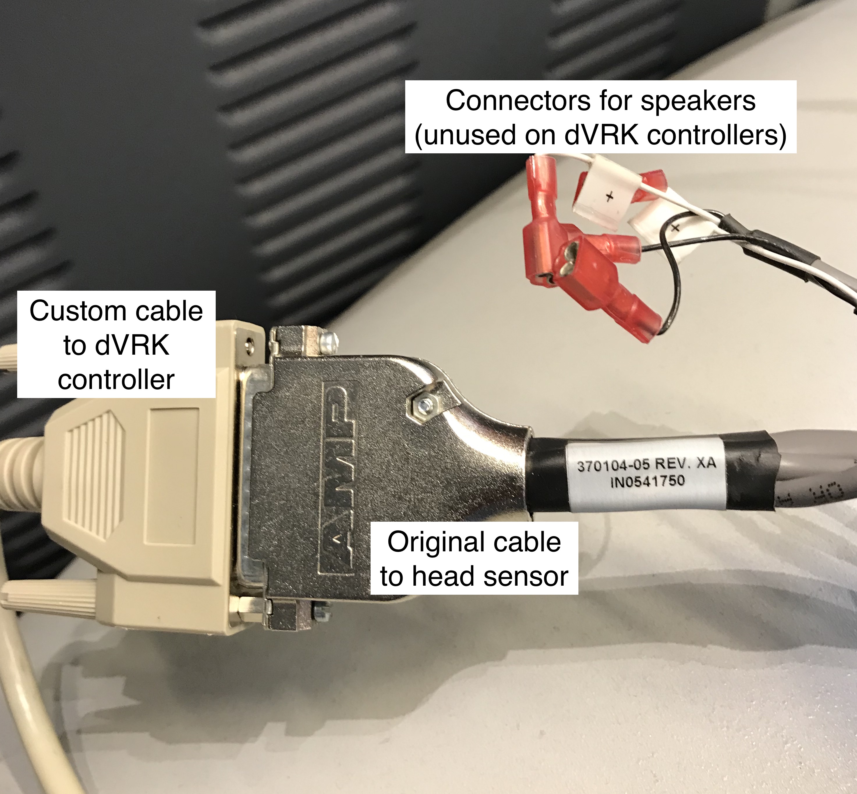
da Vinci Classic head sensor connected
Testing with qladisp
The HD-15 connector can be plugged on one of the “DOF” connectors on
the back of the dVRK controller. For the following section, we assume
the head sensor is connected to “DOF 1” on a PSM3 controller. This
means that it will be interfaced using the IOs for the first axis on
the first board on the PSM3 controller, i.e. board ID is 10. To test
the head sensor, start qladisp 10. You can test your head sensor
on any controller, just replace the 10 by the first board ID in
the controller you’re using.
Then, one can turn on/off the LEDs using the key ‘0’ to toggle. The
least significant bit of DigOut in qladisp should toggle between
1 (off) and 0 (on). When turned on, motion between the LEDs and
the sensors should be displayed as the least significant bit in the
Home, PosLim, NegLim and EncI fields. When the light is
blocked, the value should be 1:
Sensor 1:
Home, Bit Id 0Sensor 2:
PosLim, Bit Id 0Sensor 3:
NegLim, Bit Id 0Sensor 4:
EncI, Bit Id 0
Configuration
To configure your console, see head sensor configuration.