dVRK Head Sensor
Hardware
1 Digital Distance Sensor 10cm (http://www.pololu.com/product/1134)
20 Molex pin connectors (Digikey Part No. WM2510-ND - we only need 6 pin connectors)
12-feet S-Video Cable or any 3 wire cable would work (we just happened to have an old S-Video cable handy)
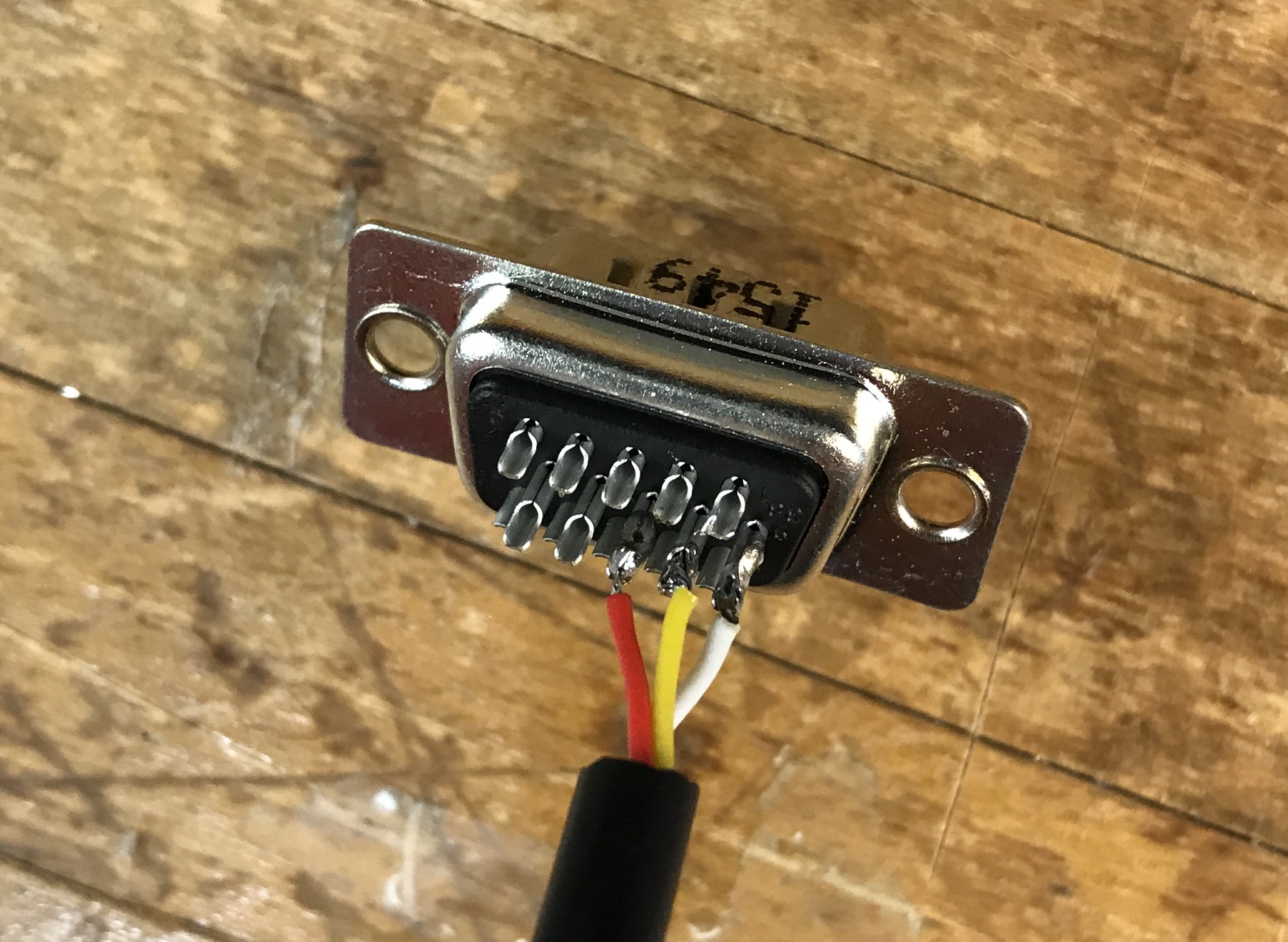
1 male DB 15 connector (for the connection to the dVRK controller)
1 3-pin right angle connector (for the connection on the sensor side)
Wiring
Sensor |
Cable |
Controller (J18, aka DOF 4) |
|---|---|---|
VIN |
Red |
Pin 8 (VCC-CON-A 5V) |
GND |
White |
Pin 6 (GND) |
OUT |
Yellow |
Pin 7 (HOME4) |
Notes:
J18 is a 15-pin connector labelled DOF 4 on the back of the dVRK controller
Please connect head sensor and foot pedal on same controller box
Physical setup
Setup option 1: base
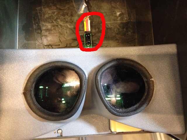
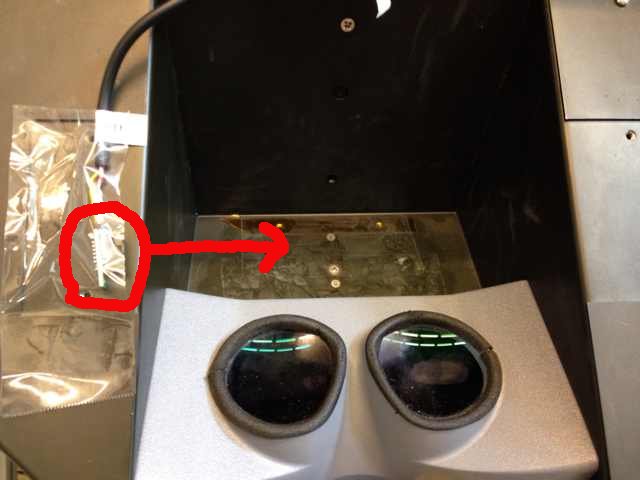
Setup option 2: side
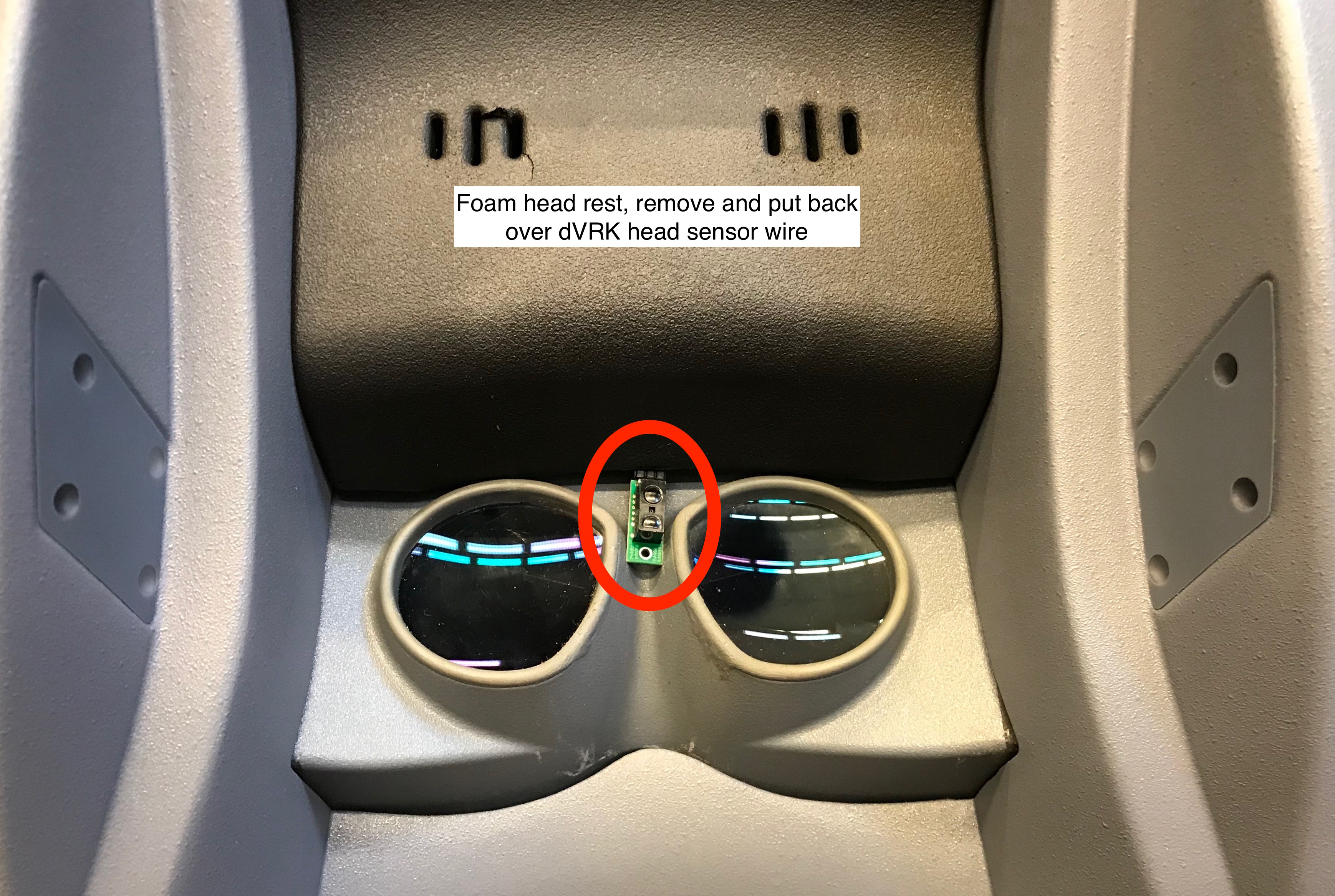
Setup option 3: full surgeon’s console. If you have a full da Vinci, you can pull the forehead foam pad and stick the wire underneath. Alternatively you can make a custom cable and use the original da Vinci head sensor (see above).
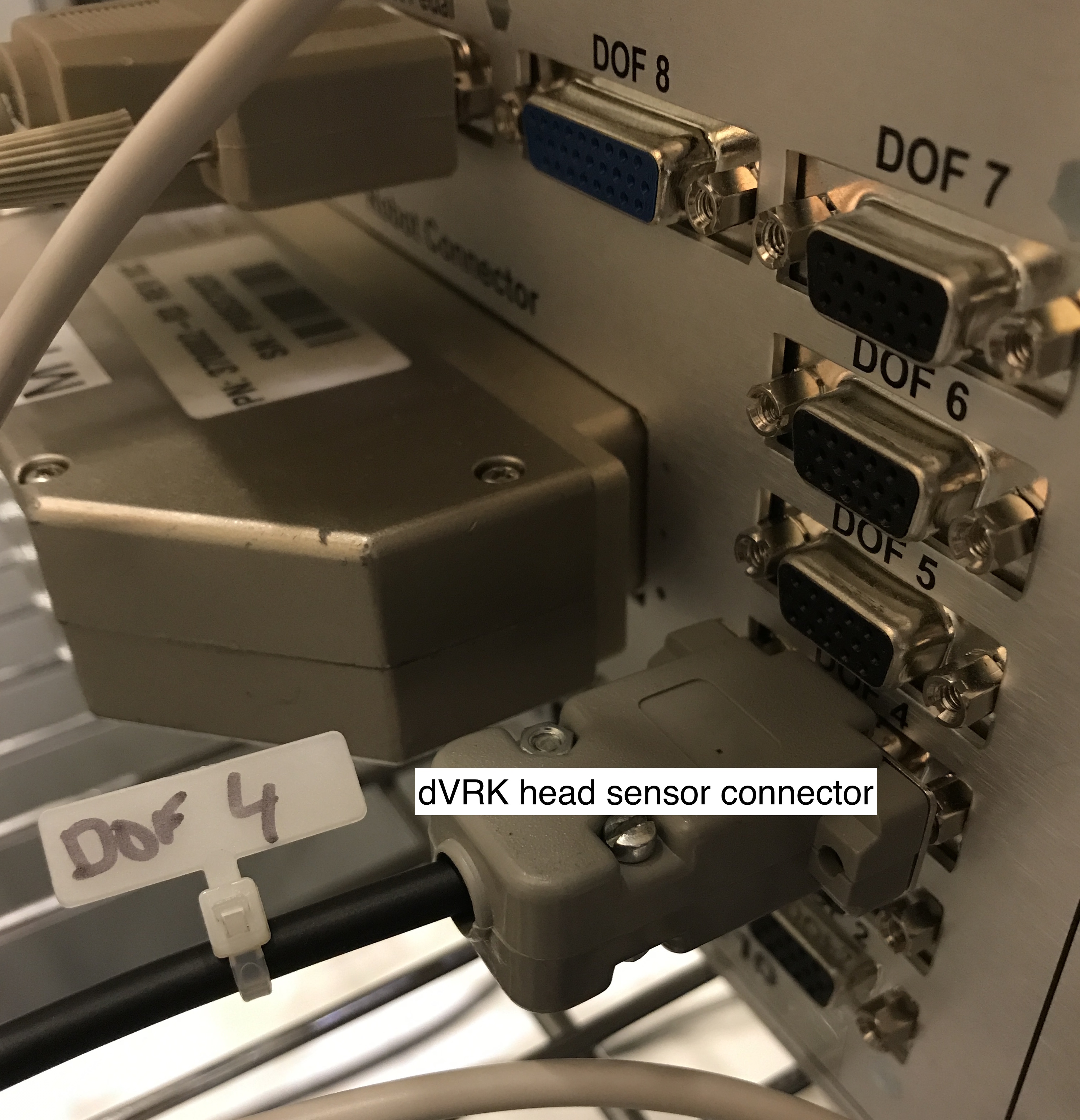
Connector for controller box, connect to DOF 4 on controller with the foot pedals (to use default config files)
Configuration
To configure your console, see head sensor configuration.