Dallas driver interface
This section describes the Dallas driver interface, which requires FPGA Firmware Version 8, because that is expected to become the preferred interface. We expect that it will be more robust than the FPGA 1-wire interface, and it will also work with all versions of controller hardware.
Prerequisites
Reading the instrument info via the Dallas driver interface requires:
dMIB Rev F or newer, or a modified dMIB Rev A-E (see below)
FPGA Firmware Version 8 or newer
dVRK software 2.0 or higher
The dMIB versions are printed on the silkscreen on both boards. To locate the dMIB, see Classic controller internal layout.
Hardware batches/builds can be found for each system in the list of dVRK sites and controller versions.
If your dVRK controller is shipped later than 2019, you do not need to modify anything but make sure the jumper is not missing. You should have dMIB Rev F or greater and the instrument info is supported out of the box (see following section).
Otherwise, you can modify your controller as described in the next section (dMIB Rev A-E).
dMIB Rev F or newer
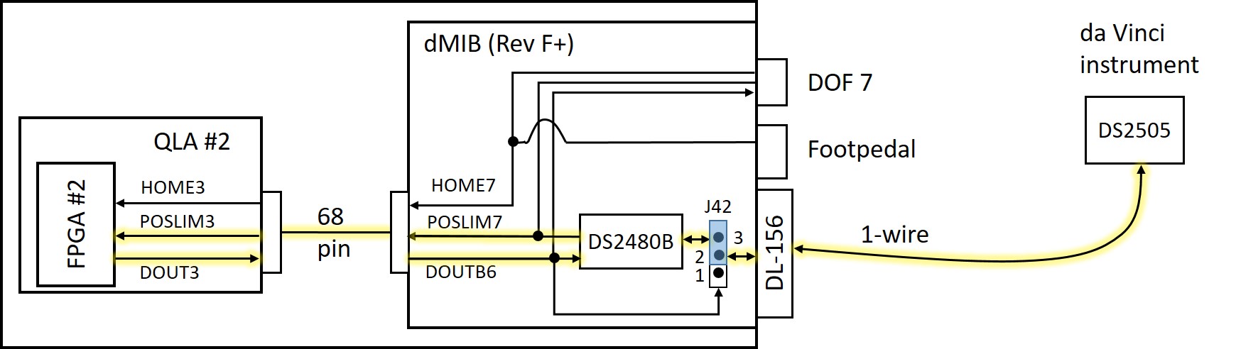
The above figure illustrates the tool interface using the Dallas driver chip (DS2480B) that is located on dMIB Rev F or greater, with yellow highlight on the active wires. The POSLIM3 and DOUT3 signals from QLA #2 (which become POSLIM7 and DOUTB6 on the dMIB) provide a serial interface to the DS2480B, which then drives the bidirectional 1-wire interface to the DS2505 chip inside the da Vinci instrument.
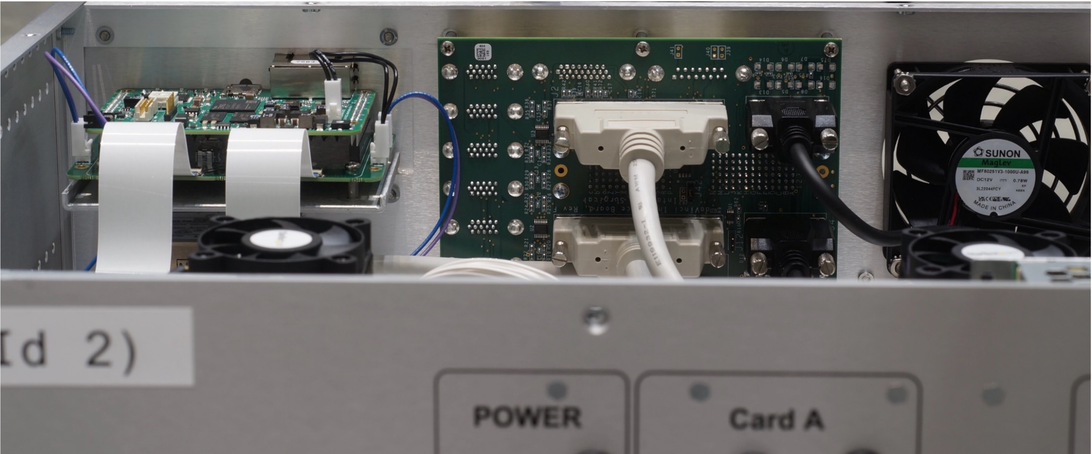
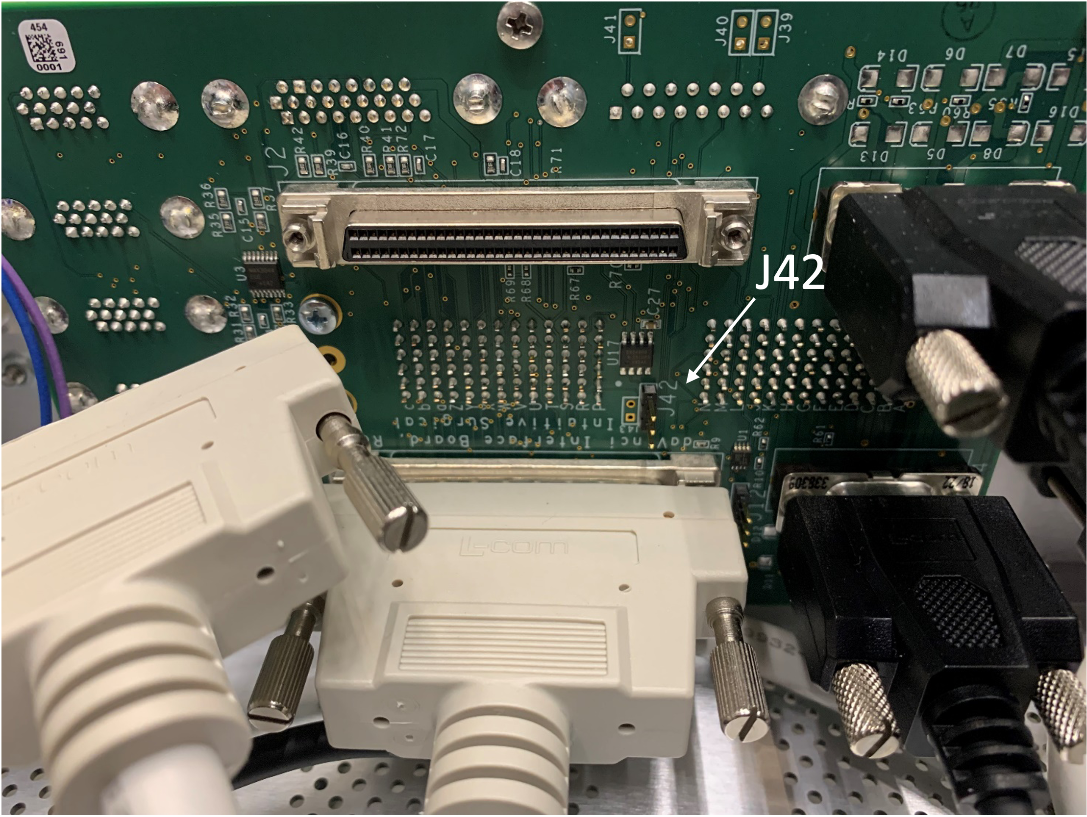
Note that it is necessary to install a jumper on J42, which is located between the two SCSI-68 cables on the internal face of the dMIB. The dMIB is mounted vertically near the center of the back of the controller (see image below). You do not need to remove the dMIB from the controller to access the jumper.
To get a better access to the jumper, you can disconnect the SCSI 68 connector but this is not required.
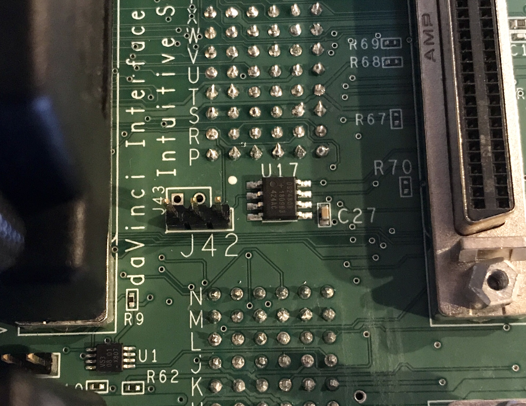
To use the dMIB Dallas driver instead of the one-wire interface, it is necessary to jump pins 2 and 3 (right-most two pins).
dMIB Rev A-E
Warning
Do not do this if you have a recently built controller (with dMIB Rev F or newer)
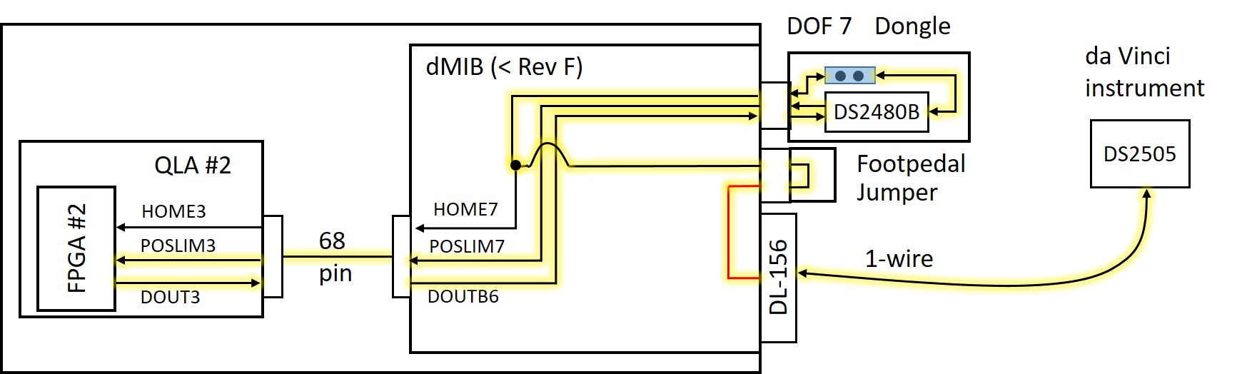
The above figure illustrates the tool interface using the Dallas driver chip (DS2480B) that is located on a dongle connected to the DOF 7 HD15 connector on the rear of the controller (J20 on the dMIB schematic), with yellow highlight on the active wires. The POSLIM3 and DOUT3 signals from QLA #2 (which become POSLIM7 and DOUTB6 on the dMIB) provide a serial interface to the DS2480B, which then drives the bidirectional 1-wire interface. The path for the 1-wire signal is somewhat convoluted – it is first connected to the HOME7 signal (assuming the jumper on the dongle is installed). The HOME7 signal is also present on the foot pedal connector and the jumper plug on the foot pedal connector routes this signal to pin 9, which is normally not used. A jumper wire, soldered on the dMIB (see below), connects foot pedal pin 9 to the 1-wire signal on the DL-156 connector.
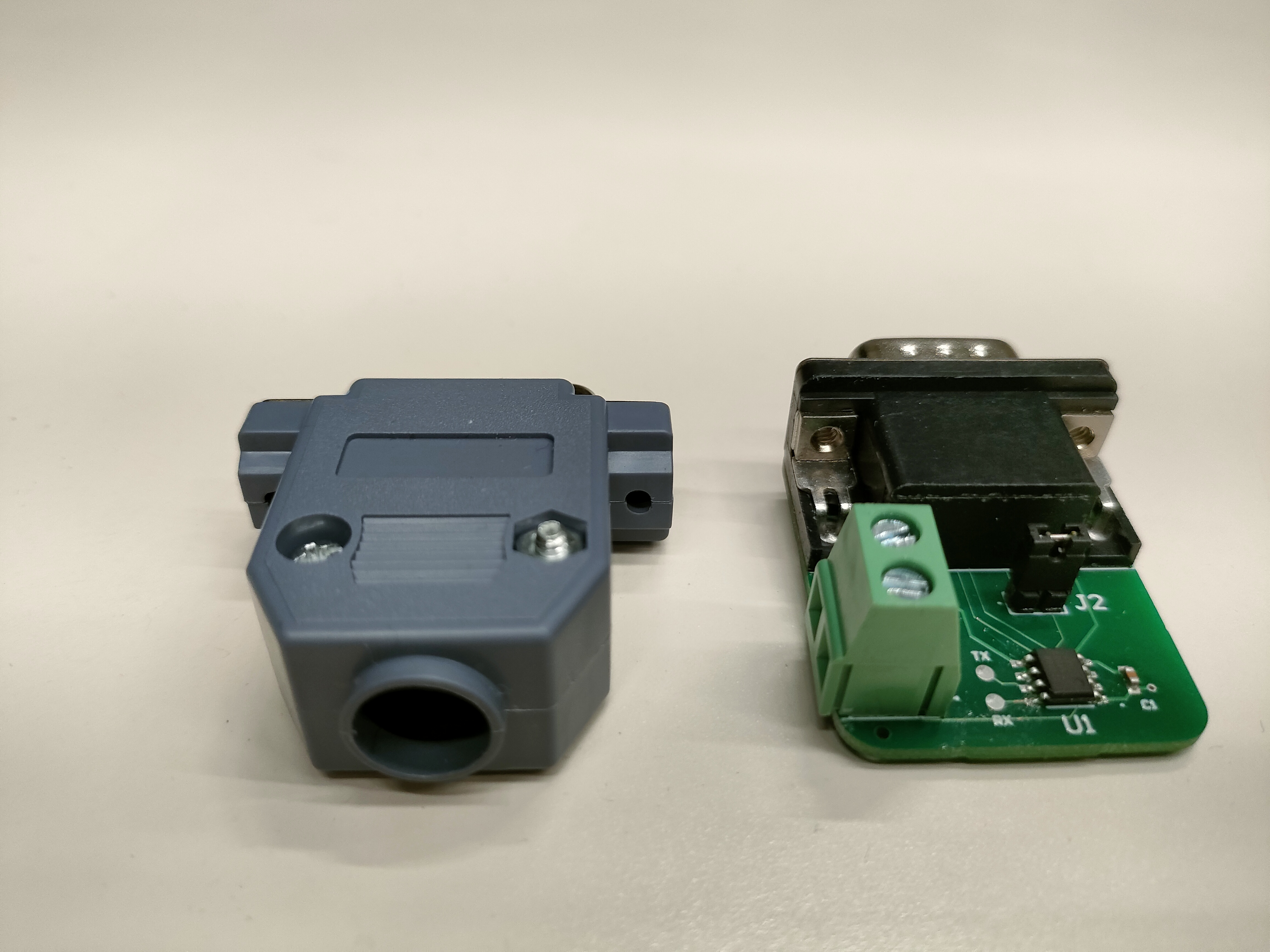
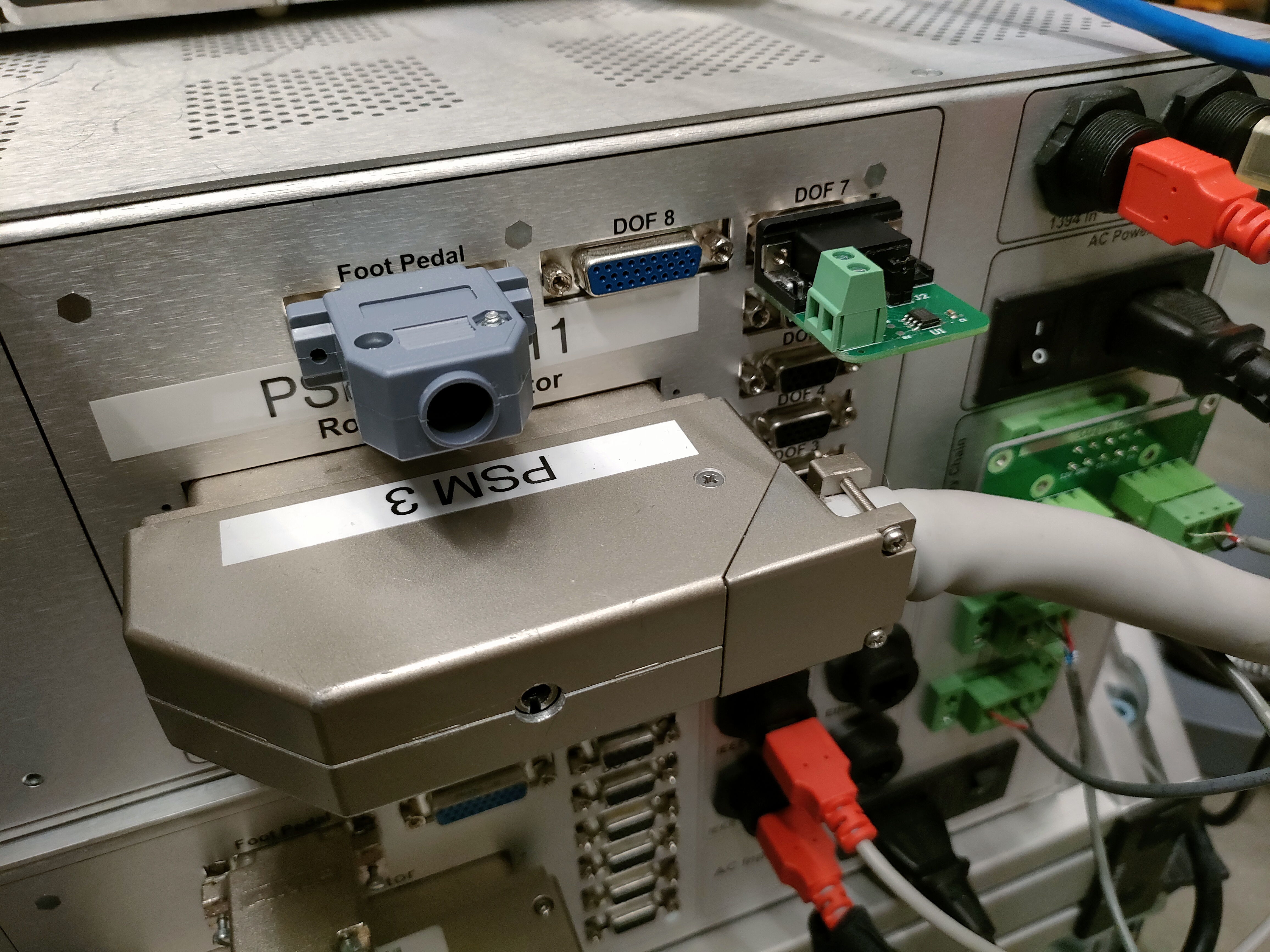
The actual dongle set and setup on a physical controller box, as an example, are shown in the following figures.
While it would have been possible to solder the jumper wire directly from the DL-156 connector to HOME7 (and eliminate the jumper plug on the foot pedal connector), the downside of that approach is that the modification would interfere with operation of the foot pedal connector, even if the DS2480B dongle is removed.
This option requires the following modifications:
Solder a jumper wire on the dMIB inside the controller box (see below)
Install a dongle on the DOF 7 (HD15) connector on the rear of the controller box (see figure above)
Install a jumper plug on the foot pedal connector (DB15) on the rear of the controller box (see figure above)
You need the PSM dVRK controllers, screwdrivers/nut drivers/hex wrenches, a piece of small insulated wire or magnet wire, and a soldering iron.
Step 1. Unplug power. Unplug cables from the dMIB/QLA, so you can work on the back side of the 156-pin ITT Cannon connector (that mates with the robot arm connector) or take the dMIB out. Please make sure to label the cables as you unplug them.
Step 2. (optional) Remove dMIB from the PSM dVRK controller box. This step may be optional if you have small dexterous fingers and good soldering skills (or use the EndoWrist soldering iron).
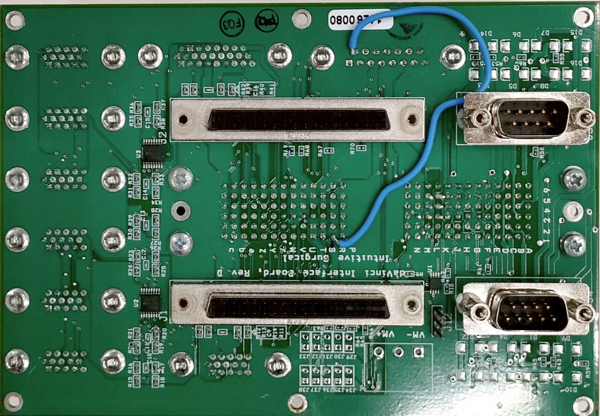
Step 3. See the figure below. Solder a jumper wire between the ‘R1 pin’ in the 156-pin connector (J3) and the top left pin, aka pin 9, in the ‘foot pedal’ DB-9 connector (J24). Some dMIB have misaligned silkscreen for the 156-pin connector, like the rev. D in the figure.
Step 4. Reconnect the cables between QLA and dMIB. Connect the PSM and test the functionality. Reassemble the controller box.