1-wire interface
This page describes the (soon to be deprecated) FPGA 1-wire interface to the DS2505 chip inside the da Vinci instruments. Reading this chip enables the software to automatically determine which tool is installed on the PSM. The recommended approach is the Dallas driver interface described here.
Prerequisites
Reading the instrument info via the FPGA 1-wire interface requires:
dMIB Rev F or newer, or a modified dMIB Rev A-E (see below)
FPGA Firmware Version 7 or newer
QLA Version 1.4 or greater
dVRK software 2.0 or higher
The dMIB versions are printed on the silkscreen on both boards. To locate the dMIB, see Classic controller internal layout.
Hardware batches/builds can be found for each system in the list of dVRK sites and controller versions.
Otherwise, you can modify your controller as described in the next section (dMIB Rev A-E).
dMIB Rev F or newer
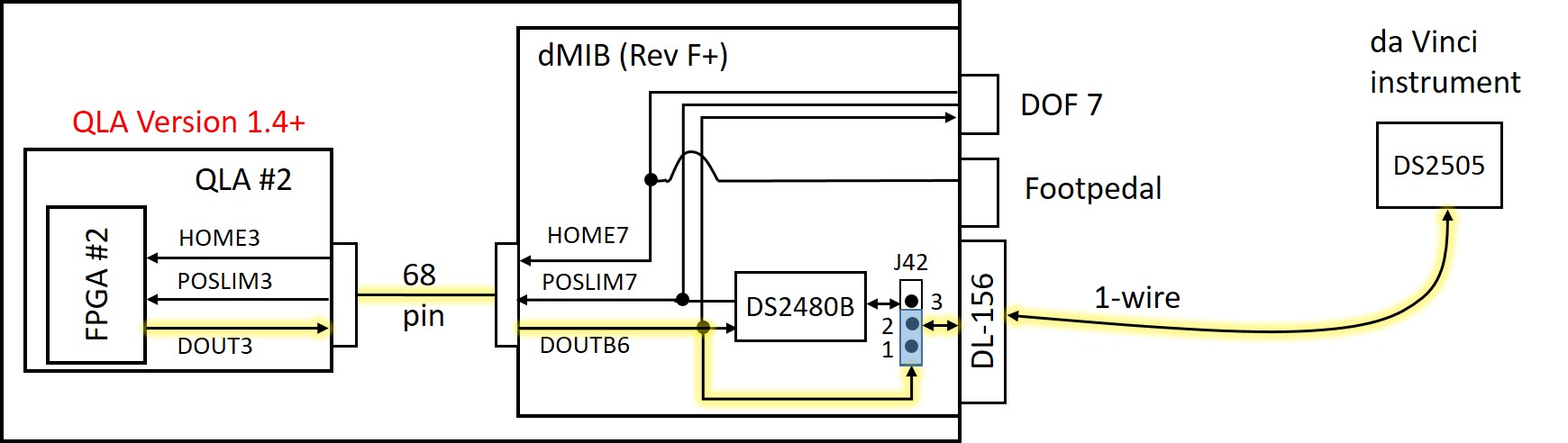
The above figure illustrates the tool interface using the FPGA 1-wire interface, rather than the Dallas driver chip (DS2480B), with yellow highlight on the active wires. The DOUT3 signal from QLA #2 (which becomes DOUTB6 on the dMIB) directly drives the bidirectional 1-wire interface to the DS2505 chip inside the da Vinci instrument.
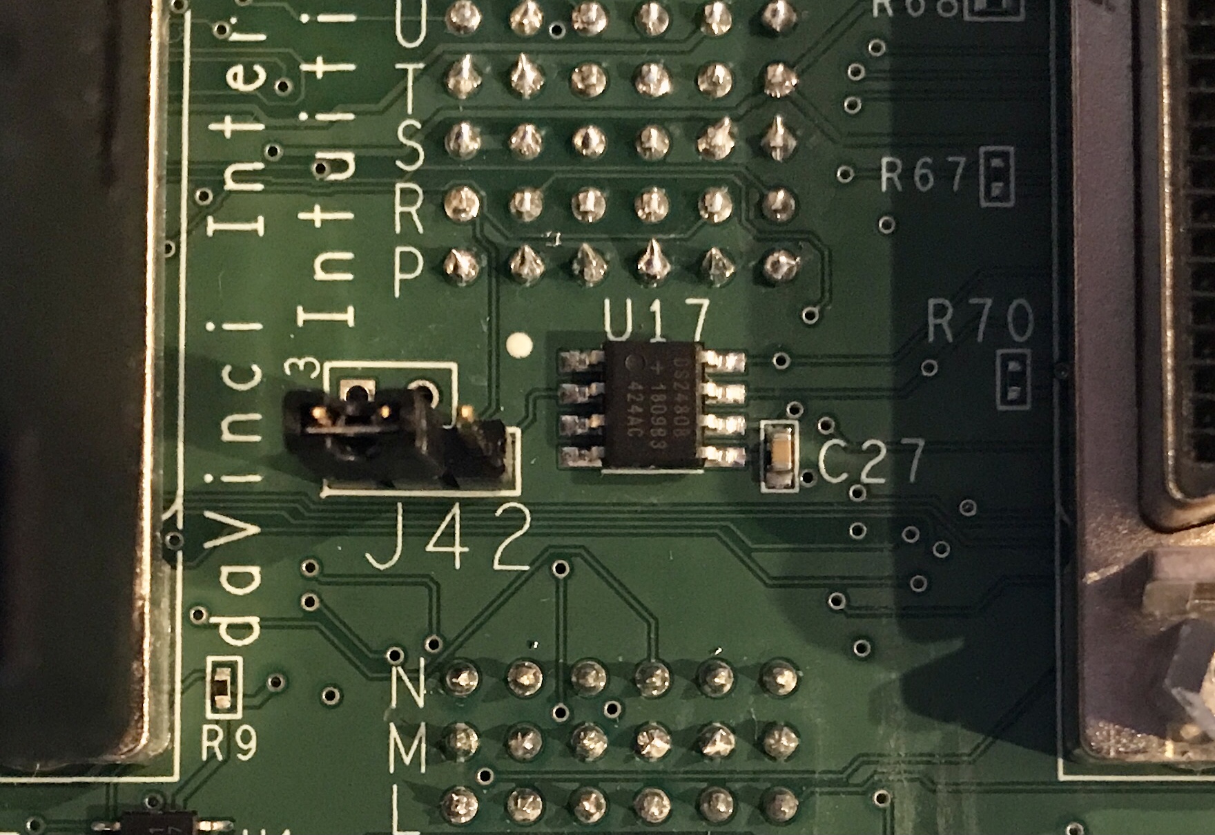
To configure the dMIB to use the FPGA 1-wire interface, you need to jump the first 2 pins on J42, which is located between the two SCSI-68 cables on the dMIB (see picture below).
dMIB Rev A-E
Warning
Do not do this if you have a recently built controller (with dMIB Rev F or newer)
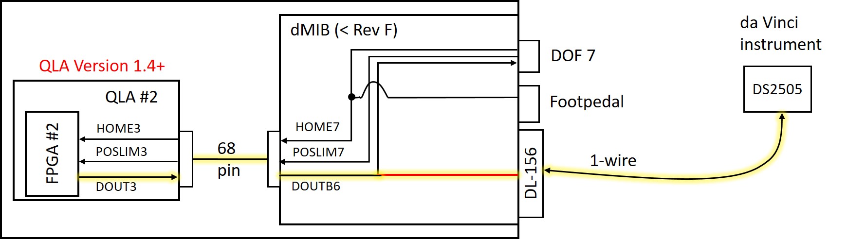
The above figure illustrates the tool interface using the FPGA 1-wire interface on dMIB versions prior to Rev F, with yellow highlight on the active wires. The DOUT3 signal from QLA #2 (which becomes DOUTB6 on the dMIB) directly drives the bidirectional 1-wire interface to the DS2505 chip inside the da Vinci instrument. This requires a jumper wire (shown in red above) to be soldered on the dMIB inside the controller box, as described below.
You need the PSM dVRK controllers, screwdrivers/nut drivers/hex wrenches, a piece of small insulated wire or magnet wire, and a soldering iron.
Step 1. Unplug power. Unplug cables from the dMIB/QLA, so you can work on the back side of the 156-pin ITT Cannon connector (that mates with the robot arm connector) or take the dMIB out. Please make sure to label the cables as you unplug them.
Step 2. (optional) Remove dMIB from the PSM dVRK controller box. This step may be optional if you have small dexterous fingers and good soldering skills (or use the EndoWrist soldering iron).
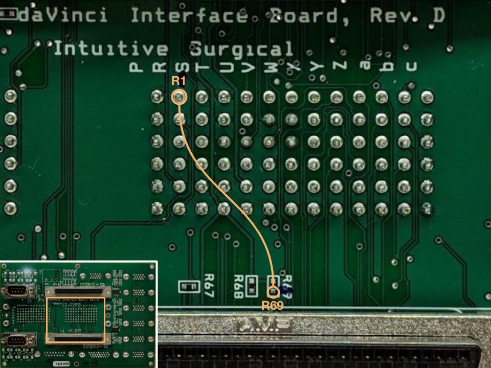
Step 3. See the figure below. Solder a jumper wire between the ‘R1 pin’ in the 156-pin connector and the resistor ‘R69’ pad that is closest to the SCSI connector. Some dMIB have misaligned silkscreen for the 156-pin connector, like the rev. D in the figure. Do not remove the resistor R69. If you did so and cannot solder the original part back in, you can jump an approximately 1 kOhm resistor between the ‘R69’ pad you connected the jumper wires to and the ‘T6 pin’ of the 156-pin connector.
Step 4. Reconnect the cables between QLA and dMIB. Connect the PSM and test the functionality. Reassemble the controller box.