
2.2.2.3. Internal layout
FPGA V1/V2 based
Internally, each V1 or V2 QLA1-based controller box contains two FPGA/QLA board sets, one dMIB (da Vinci Manipulator Interface Board), LED boards, power supplies and relays.

QLA, FPGA V1 based Classic controller layout
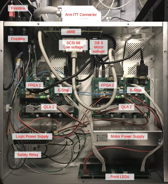
QLA, FPGA V1 based Classic controller internals (PSM with single motor power supply)
Note
In the picture above, an astute reader might notice that the QLAs are missing the now recommended heat-sink and fan.
FPGA V3 based
The V3 DQLA1-based controllers contain one FPGA V3 and 2 QLA boards, a set of DQLA-Q/DQLA-F (connected using 2 flat ribbons), one dMIB (da Vinci Manipulator Interface Board), LED boards, power supplies and relays. The FPGA is mounted against the controller’s back panel, so we can use the FireWire and Ethernet ports directly. The DQLA-F board mounted under the FPGA is also butting against the back of the controller and provides the 4 and 5 pins connectors for the e-stop.
Compared to the QLA1-based controllers, this greatly reduced the amount of internal wiring (Ethernet and FireWire pass-through cables, safety relays).

DQLA, FPGA V# based Classic controller layout
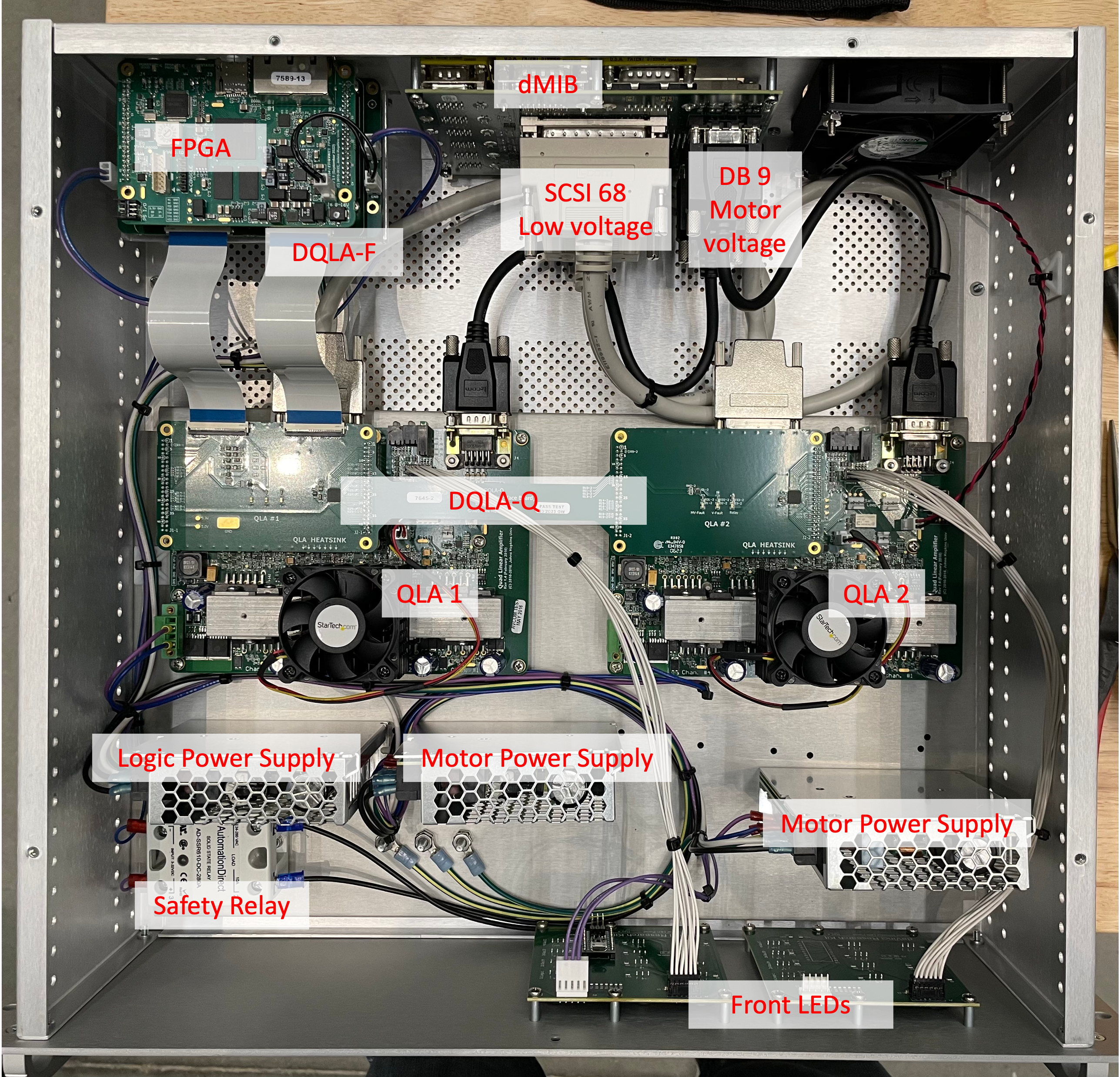
DQLA, FPGA V3 based Classic controller internals (MTM with 2 motor power supplies)