3.3.4.9. Custom IOs
Introduction
The dVRK Classic controllers use a pair of QLA boards with either two logic boards (FPGA V1, V2 or V3, known as QLA1) or a single logic board (FPGA V3, known as DQLA). The QLA boards were originally designed to drive different types of experimental robots at Johns Hopkins. Each board provides the necessary inputs and outputs to drive up to 4 motors. This includes the following:
Outputs:
1 motor power
1 digital output
Inputs:
1 differential encoder
1 analog input (used for potentiometers and Hall Effect gripper on MTMs)
4 digital inputs for limit/home switches (used to detect sterile adapter, instruments, buttons…)
Since the dVRK Classic arms only need 7 power lines (7 actuators for PSMs and MTMs, 4 actuators and 3 brakes for ECMs), it is possible to use the 8th channel to control an extra actuator. Some limit/home switches are also unused by the dVRK.
The hardware exposes all these IOs through the dSIB’s Foot Pedal and DOF connectors (see dVRK Classic controllers). It is possible to use any spare IOs for a custom device provided you build your own cable.
Connectors
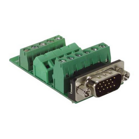
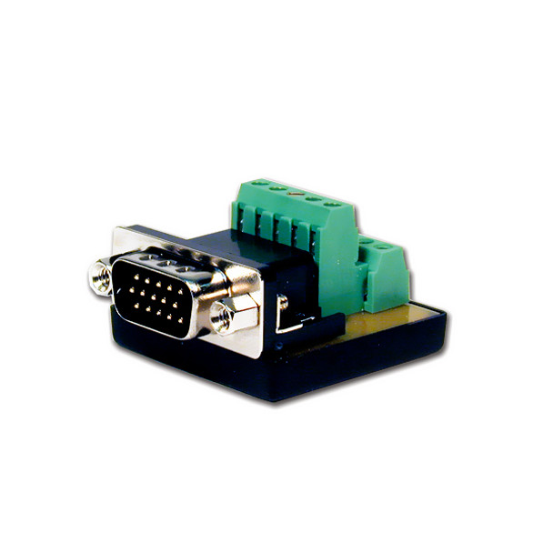
The DOF connectors use a standard D-Sub Connector 15-pin HD15 (aka VGA connector). For prototyping, you can use the following:
Configuration
All IO configuration files are JSON based. They are loaded by the
sawRobotIO1394 components. Examples can be found in the shared dVRK
directory: sawIntuitiveResearchKit/share/io. For a single digital input,
your configuration file should look like:
{
  "$id" : "saw-robot-io.schema.json",
  "$version" : "6",
  "digital_inputs" :
  [
    {
      "bit_id" : 0,
      "board_id" : 3,
      "debounce_time" : 0.2,
      "name" : "clutch",
      "pressed_value" : true,
      "trigger_when_pressed" : true,
      "trigger_when_released" : true
    }
  ]
}