
2.2.2.2. Exterior
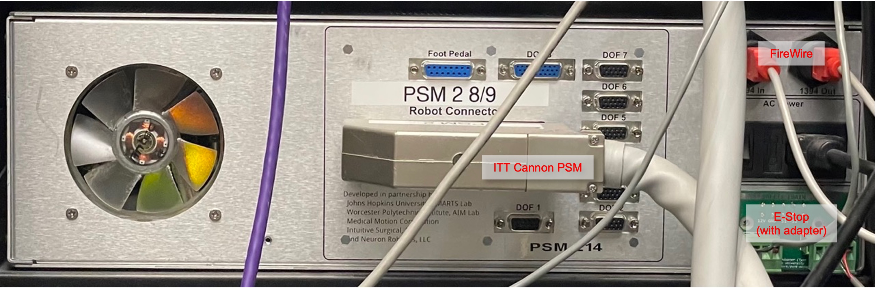
Connectors
One AC power connector, with on/off switch
One 156-pin connector ITT Cannon (for the MTM, PSM, or ECM)
Two FireWire connectors
Two Ethernet connectors (V2 and V3 controllers)
One or two 4 or 5-pin safety chain connectors (depending on version); see E-Stop
One DB15 foot pedal connector; see dMIB I/O
Seven HD15 expansion connectors and one HD26 expansion connector; see dMIB I/O
One SD card slot for the firmware and user applications (V3 controllers)
Back of QLA, FPGA V1 based Classic controller (no Ethernet)
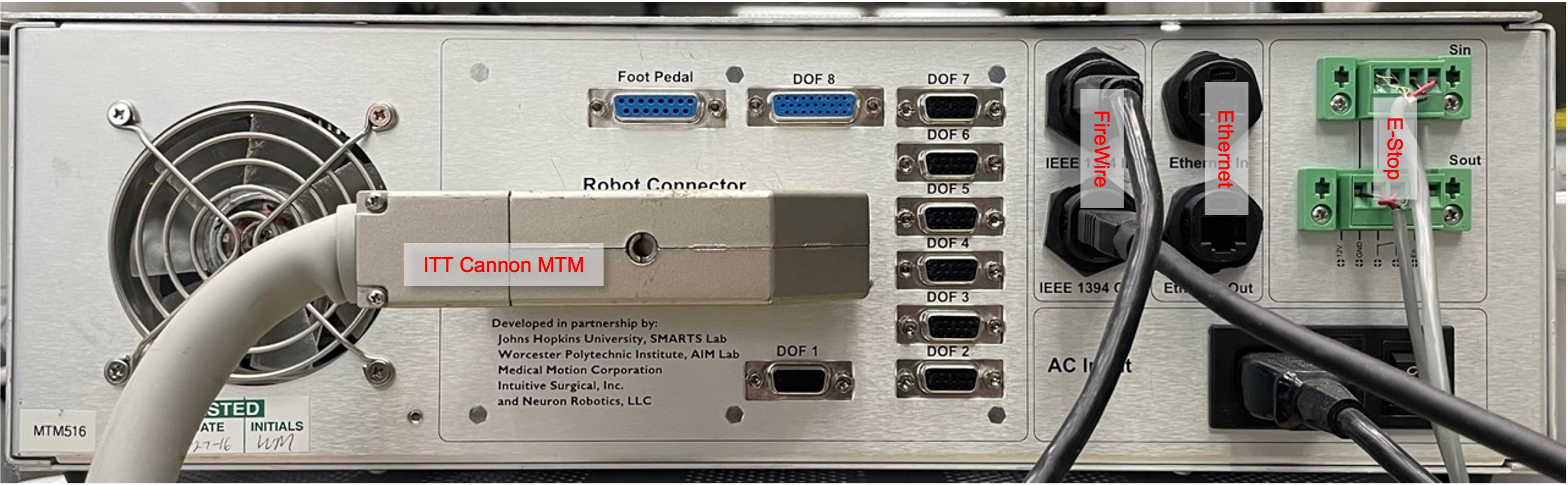
Back of QLA, FPGA V2 based Classic controller
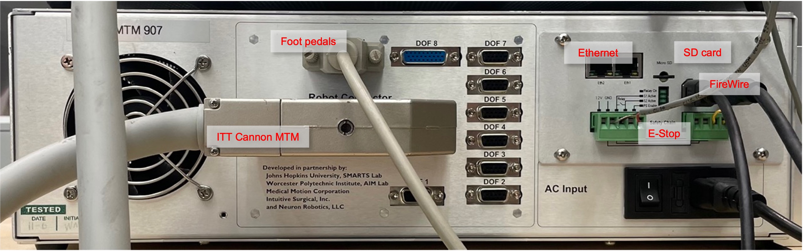
Back of DQLA, FPGA V3 based Classic controller
Note
The Foot Pedal and DOF connectors can be used to connect peripheral devices using digital inputs and outputs such as focus controller, head sensors… (dVRK Classic custom IOs). Furthermore, since the dVRK arms use only 7 out of the 8 axis on the FPGA/QLA, it is possible to use the 8th DOF to control an extra motor (spare power, encoder, potentiometer and home/limit switches).
LEDs
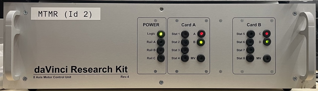
The dVRK Classic controllers have LEDs grouped in different sections, Power and Card(s).
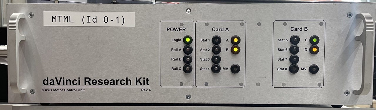
Front of QLA, FPGA V2 based Classic controller (2 board IDs)
Front of DQLA, FPGA V3 based Classic controller (1 board ID)
Power
The power LED logic is controlled by the two boards mounted on the front panel of the controllers. The details can be found on WPI page from the ISI Research Wiki
The LEDs are:
Logic: power used for the FPGA board, i.e. on board computing/logic
Rail A/B: power supplies used for motor control (see details above). MTM controllers have two different motor power supplies so the Rail A and B LEDs are meaningful, PSM, ECM and SUJ controllers use a single motor power supply, so the only meaningful LED is Rail A. Rail A/B, i.e. motor power, can be turned on/off using a PC and need the safety chain to be closed.
In general, the LEDs for power follow the following convention:
Flashing Red - no power V<1V
Solid Red - voltage present but too low, below VS_min
Solid Green - voltage present, between VS_min & VS_max
Solid Orange (Red & Green) - voltage present but too high, above VS_max
Cards A and B
These LEDs replicate the LEDs from the QLA boards.
The LEDs A/B (or C/D for the second card) are used to show that the firmware is fully loaded. When the firmware is fully loaded both LEDs will go back and forth between red and green
The LED MV is for Motor Voltage. It should turn to green when motor power is requested
The 8 LEDs (4 for Card A and 4 for card B) labelled either “Fault” (older controllers) or “Status” (recent controllers) turn red when an axis is powered. When powered on, there should be 7 red LEDs for the MTM, PSM and ECM controllers and 4 for the SUJ controller. With software version 1.7 and lower, there should be 8 red LEDs for MTM controllers