8.1.5. PSM third joint potentiometer offset
8.1.5.1. Introduction
Please read the potentiometers calibration for the overall motivation.
Potentiometer offset calibration is crucial to get the best possible accuracy for all dVRK manipulators. Amongst the different dVRK manipulators (MTMs, PSMs and ECM), we should pay special attention to the PSM accuracy since the reported position is often used for research projects going from machine learning to autonomous motion.
The PSM has 7 actuators, corresponding to 6 joints used for the kinematic chain and one extra to control the jaws:
Actuators 1 and 2 correspond to the first two joints of the kinematic chain. Errors in zero position for these actuators will lead to a “rocking” of the reference frame around the RCM point and shouldn’t affect the relative accuracy of the PSM. Since most applications would require some kind of registration of the PSM with respect to the task’s coordinate system, the registration method should compensate for these errors. Therefore, we’re going to ignore these for now.
Actuator 3 corresponds to the instrument insertion stage (roughly up/down translation). There is no obvious mechanical way to identify where the joint should be when set to zero. Errors on the third potentiometer offset will lead to a spherical deformation of the cartesian space. For example, a straight line would be measured as an arc. This is the issue we’re going to address here.
Actuators 4 to 7 correspond to the last 3 joints of the kinematic chain and the jaws. There is an easy solution for these.
The calibration procedure can either be carried out manually, or automatically if you are willing to mark the joint 5 axis screw with nail polish. Either method will require a camera for either you or the computer to measure the calibration error. The manual method is simpler and the results can be as good as the automatic method if you are careful.
8.1.5.2. Manual method
Introduction
The main idea is to use the fact that the insertion stage controls the distance to the RCM point (Remote Center of Motion, aka fulcrum point) of the PSM. So if we can attach an instrument to the PSM and position the joint 3 so that a given feature of said instrument is positioned on the RCM, motions on the first 2 joints should not affect the absolute position of said feature. In other words, if the depth is incorrect (based on potentiometer #3 offset), moving the PSM along joint 1 or 2 will make the feature on the instrument move along a curved surface.
For this procedure, the idea is to insert an instrument and let the PSM rock back and forth around the first joint (side to side) while monitoring the absolute position of a given feature on the instrument.
For the feature, we picked the first axis of the EndoWrist (joint 5). It is a pretty easy axis to locate, and it is rigidly attached to the shaft so its distance to the RCM point is only affected by the 3rd actuator. The fourth joint (rotation along the shaft) can be used to align the 5 joint’s axis with the first joint’s axis (90-degree rotation from 0)
To track the absolute 3D position of the feature, we recommend using a camera on a tripod connected to your computer. This way you can place some “marker” on your screen and make sure the feature is not moving
To determine the range of the rocking motion, the script provided will first let the user rock the PSM by hand and record the minimum and maximum values one can use for the first joint. This is so each group can adjust the range of motion to the amount of free space around their PSM.
Finally, while the arm is rocking back and forth, the user can adjust the depth offset using the keys +/-
Since a picture is worth a thousand words, we provide a short video describing the procedure.
Requirements
dVRK 2.0 + ROS
A working system file for the PSM you need to calibrate
A camera on a tripod or fixed mount is recommended. A basic USB web camera will do fine. For Linux, most USB cameras can be used with tvtime
An 8mm da Vinci Classic instrument (e.g. Large Needle Driver, DeBakey, Micro Forceps…). The procedure won’t work with S/Si instruments since they are too long (see instruments)
An alternative to the cannula to keep the instrument aligned with the RCM point. Unfortunately the cannula covers the RCM point, so one can’t visually track the feature with it. You can use a rubber band as demonstrated in the video or even better, 3D print a support: https://github.com/jhu-dvrk/dvrk-cannulas
Procedure
Start system with
-Coption! For example:roscd dvrk_config qlacommand -c close-relays rosrun dvrk_robot dvrk_system -j <my-config-dir>/system-PSM1.json -C
Replace
<my-config-dir>and PSM name for your configuration.Home the PSM and make sure a dVRK supported Classic 8mm instrument is inserted
Start your camera and position it so you have a close view of the RCM point. Then run
tvtimein a second terminal to get the video feed on your dVRK computer (or another computer if you prefer)In a third terminal, launch the calibration script (
dvrk_calibrate_potentiometer_psm_cv.py) with thesawRobotIO1394-PSMx-xxxxx.jsoncorresponding to your PSM, something like:roscd dvrk_config/<my-config-dir> rosrun dvrk_python dvrk_calibrate_potentiometer_psm.py -a PSM1 -c sawRobotIO1394-PSMx-xxxxx.json
Follow the script instructions to find the maximum range of motion for your PSM. This step is required to accommodate PSMs installed in tight spaces and avoid collisions
As soon as you press
d(for done), the PSM will move briskly to the starting position for the rocking motion and then rock back and forth around the first jointPlace a dummy window/marker on top of feature on video and place it as close as possible to the current position of the axis 5 of the instrument (YouTube video). You can use a post-it tacked on your monitor too…
If the axis 5 is moving along an arc with a downward opening, the offset is too small so press
+in the script’s terminal to adjust it. If the motion is along an arc with upward opening, the offset is too big, press-to adjust it.Once you found the offset that minimizes the amount of motion for the joint 5’s axis, press
dSave and optionally compare the old and new files using something like meld.
The script suggests rebooting your dVRK controller. This is not necessary if you remembered to use the
-Coption for thedvrk_system(introduced with dVRK 2.0.1)Restart your dVRK system application using
-Coption and repeat the steps above. Ideally you shouldn’t have to adjust the offset
8.1.5.3. Automatic method
Introduction
The basic idea is the same as in the manual version: if we rock the PSM side to side (around the first joint) and choose the insertion depth so that the axis for joint 5 should be position at the RCM, then joint 5’s axis should not move. If it does move, we adjust the insertion calibration until it is fixed. For the computer to automatically track joint 5’s axis via a camera, the screw needs to be marked with a bright pink color.
Requirements
All the requirements for the manual method, plus…
Bright pink nail polish to mark the first axis of the EndoWrist (joint 5). If there are any bright pink or red objects directly behind the PSM you may need to move them out of the camera’s view or at least farther away. Example of pink nail polish and where to apply it shown in image immediately below.
[Optional] A diffuse light source that won’t cause much glare. This is only needed if the computer has trouble tracking the pink target. In a pinch, a phone displaying a white image (with the screen brightness on high) should suffice. You may need to remove/block bright light sources behind the PSM if they wash-out the camera.
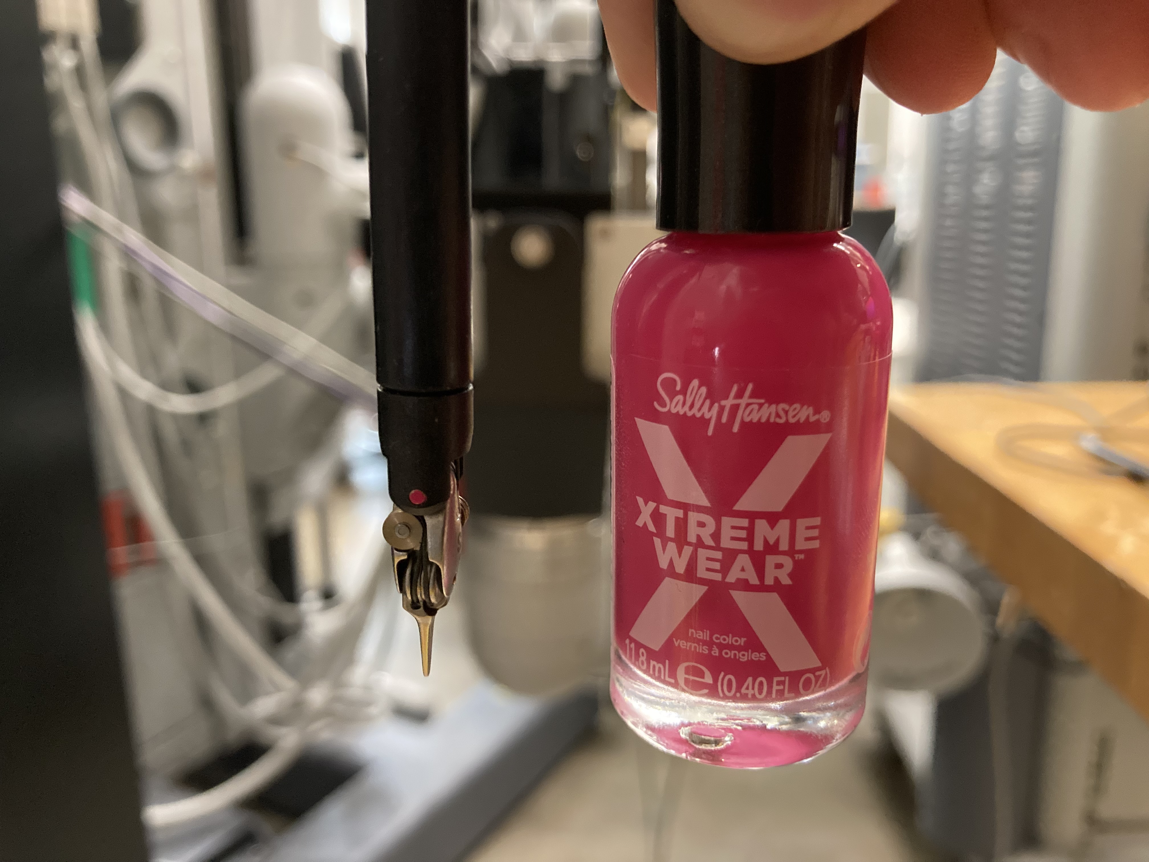
Nail polish on PSM instrument, joint 5
Procedure
Start system with
-C option! For example:roscd dvrk_config qlacommand -c close-relays rosrun dvrk_robot dvrk_system -j <my-config-dir>/system-PSM1.json -C
Replace
<my-config-dir>and PSM name for your configuration.Home the PSM and make sure a dVRK supported Classic 8mm instrument is inserted
Start your camera and position it so you have a close view (2-4 inches is ideal) of the RCM point.
In a second terminal, launch the calibration script (
dvrk_calibrate_potentiometer_psm_cv.py) with thesawRobotIO1394-PSMx-xxxxx.jsoncorresponding to your PSM, something like:roscd dvrk_config/<my-config-dir> rosrun dvrk_python dvrk_calibrate_potentiometer_psm_cv.py -a PSM1 -c sawRobotIO1394-PSMx-xxxxx.json
Follow the script’s instructions to find the maximum range of motion for your PSM. This step is required to accommodate PSMs installed in tight spaces and avoid collisions. A range of +/-70 degrees is ideal, but at least +/-50 degrees should be ok. Smaller ranges of motion may work, but may fail to work properly in some cases.
As soon as you press
d(for done), the PSM will move briskly to the starting position and beginning measuring the camera’s orientation. NOTE If the pink vision target moves out of the camera’s view during this step, either adjust the camera’s angle or move it slightly further away. You will be prompted to select the target by clicking it on the screen, to avoid tracking the wrong pink object.Next, the PSM will beginning rocking side to side and calibration will commence. At any point, if the computer loses track of the target a message will be shown in the terminal prompting you to click on the target again.
Once calibration has converged to within a threshold value (0.1 mm by default), calibration will complete. If the timeout is reached before convergence (2 minutes by default), calibration will fail. In this case, try improving lighting, camera position, etc. or increase the timeout (this can be done via a option on the calibration script, use
-t 180to raise it to three minutes). Finally, if convergence is almost reached but not quite, you could try loosening the convergence threshold, e.g. passing--threshold 0.5to raise it to 0.5 mm.The script will produce a new configuration file with the calibration result. You can compare the old and new files using something like
meld.The script suggests rebooting your dVRK controller. This is not necessary if you remembered to use the
-Coption for thedvrk_system(introduced with dVRK 2.0.1)Restart your dVRK system application using
-Coption and repeat the steps above. Ideally the script will produce a calibration within +/-0.1-0.2 mm.
8.1.5.4. Effects on positioning accuracy
Positioning accuracy of a PSM was measured, using an NDI Polaris optical tracker, with various potentiometer offsets. A mis-calibration of 4 mm resulted in over 45% increased RMSE (root-mean-square error), with typical RMSE of 1.86 mm for a calibrated PSM. For uncalibrated dVRK systems, the potentiometer offset error is often 5-10 mm, which can result in more than doubling the RMSE. Maximum error across the PSMs range of motion also decreased significantly with proper calibration.
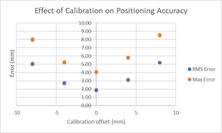
Effect of PSM potentiometer calibration on accuracy