8.1.8. SUJ potentiometers
Warning
The SUJ are not extremely precise, the position of each instrument with respect to the patient’s cart is usually reported within 50mm cube! To get a better pose estimation of each instrument and (or with respect to) the camera, you will need to use an external sensor to register the active arms. Once properly registered, the relative accuracy of the instrument’s pose should be within a couple of millimeters.
Hint
If you are calibrating your SUJs for and only for the teleoperation, the position doesn’t matter. You should only care for the orientation of each active arm base frame. This can be useful since calibrating the height is a bit tricky. A bad height estimation (calibration of SUJ translation stage, joint 0) doesn’t impact the orientation to each RCM frame.
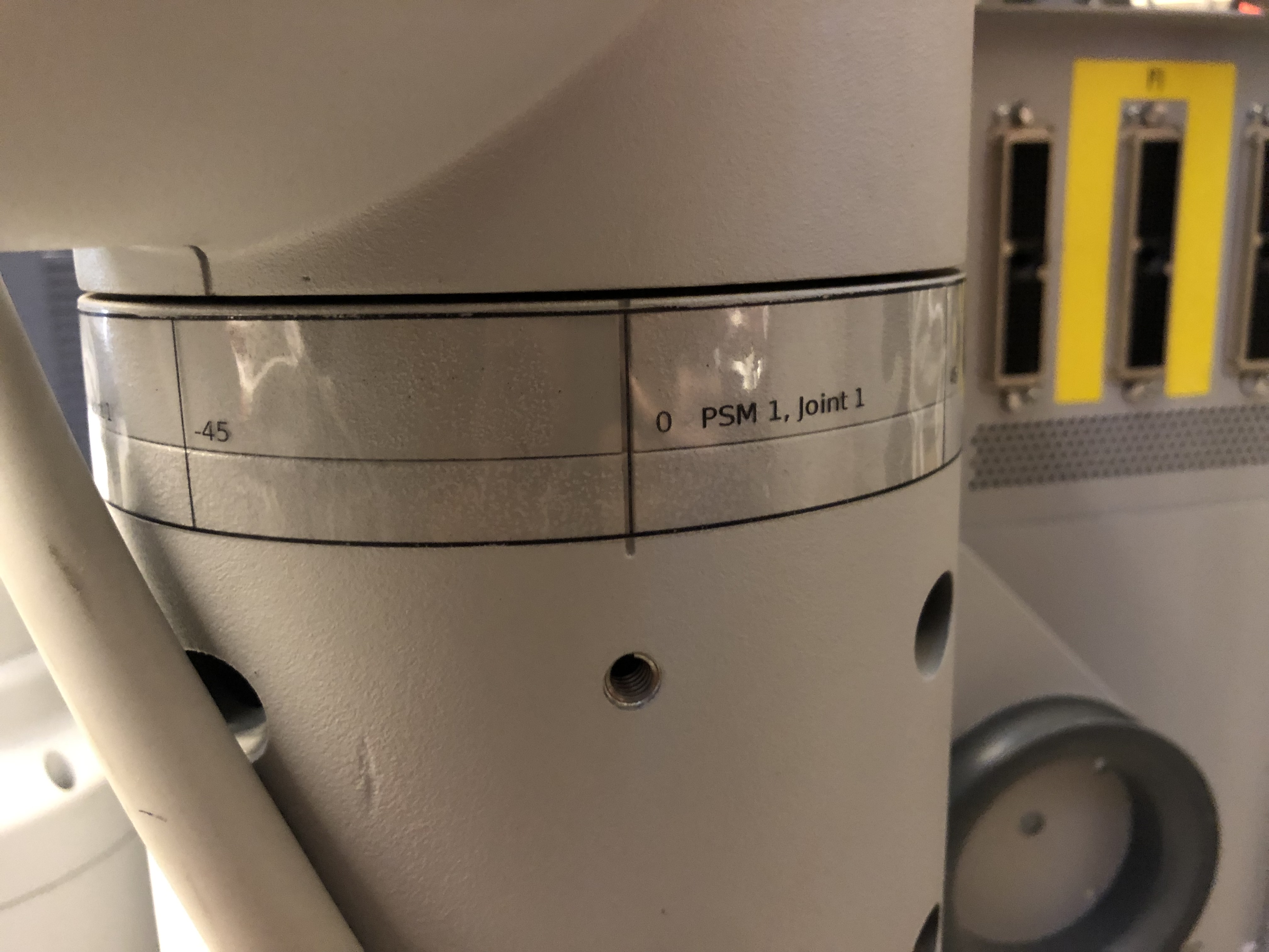
8.1.8.1. Labels
To use the SUJs with the dVRK controller and/or the dVRK software, the main challenge is to determine the current position of each joint. This has to be done if you have the dVRK controllers (for calibration) or if you plan to use the SUJs in simulation mode. Unfortunaltely, there are no graduation on the SUJ joints. To help with this task, we provide some custom labels that can be attached to each joint of the SUJs.
Physical dimensions
These dimensions are used to determine the scales on the labels.
Joints diameters:
0: Translation, we don’t know where is the origin, use the floor level
1: Rotation, vertical axis, diameter 147.5 mm, circumference 463.4 mm (all -90/+90)
2: Rotation, vertical axis, diameter 133.5 mm, circumference 419.4 mm (PSM1 -135/0, PSM2 0/+135, PSM3/ECM -90/+90)
3: Rotation, vertical axis, diameter 107.5 mm, circumference 337.7 mm (all -90/+90)
4: Rotation, horizontal axis, diameter 93.3 mm, circumference 293.1 mm (PSMs only -135/+135)
5: Rotation, “vertical” axis, diameter 89.4 mm, circumference 280.9 mm (PSMs only -135/+135)
Labels
You can download a document to print on letter paper: dVRK labels for
SUJ. The .svg file can be opened,
modified and printed using inkscape on Linux. You can also find a
pdf version if you don’t have
inkscape. Please, if you update the .svg file, make sure you also update
the .pdf and send the updated version to JHU.
We used clear polyester labels (Hemmi Papilio Supplies, Gloss White/Clear Polyester, 3 mil with permanent adhesive, SKU: HPGC/HPGW) but you can also use plain white paper with double-sided tape on the back.
After printing the labels, make sure your computer or printer didn’t scale the document to fit the paper. There is a printed reference on the labels that should measure 20 cm.
8.1.8.2. Label placement
Notes
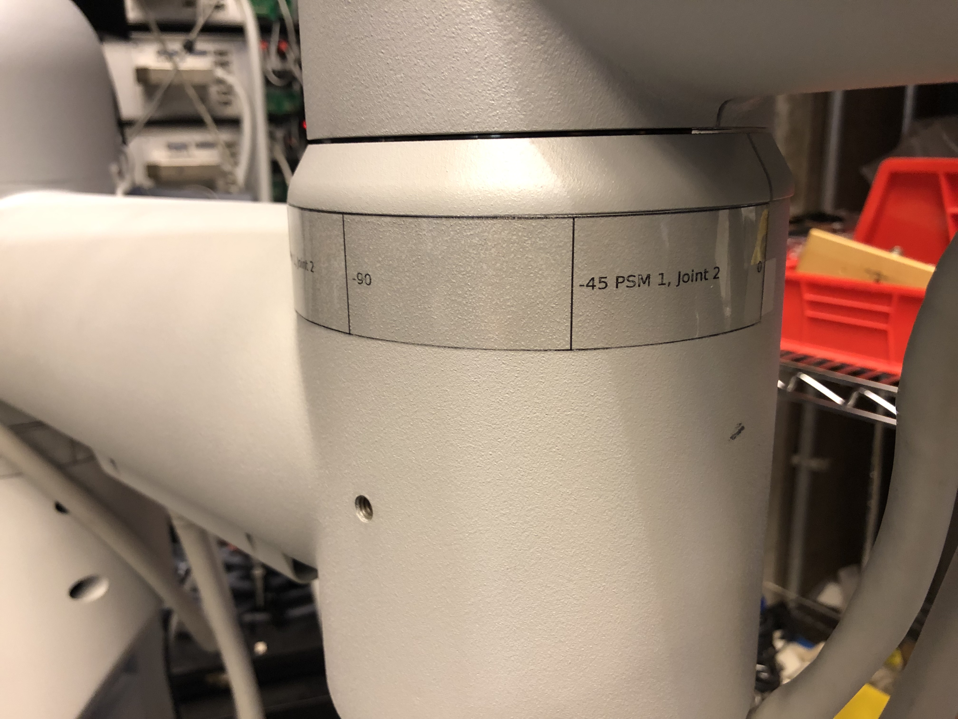
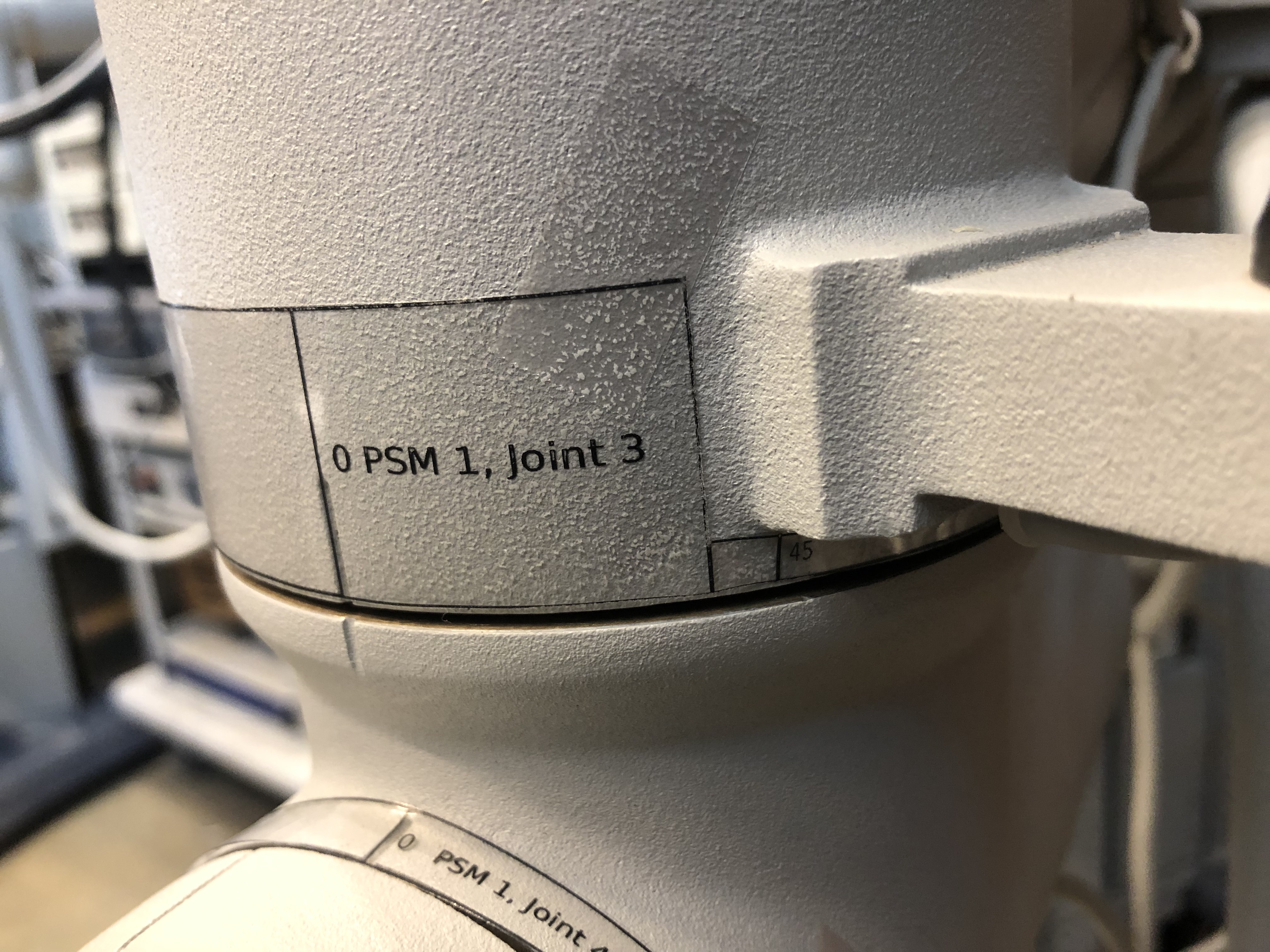
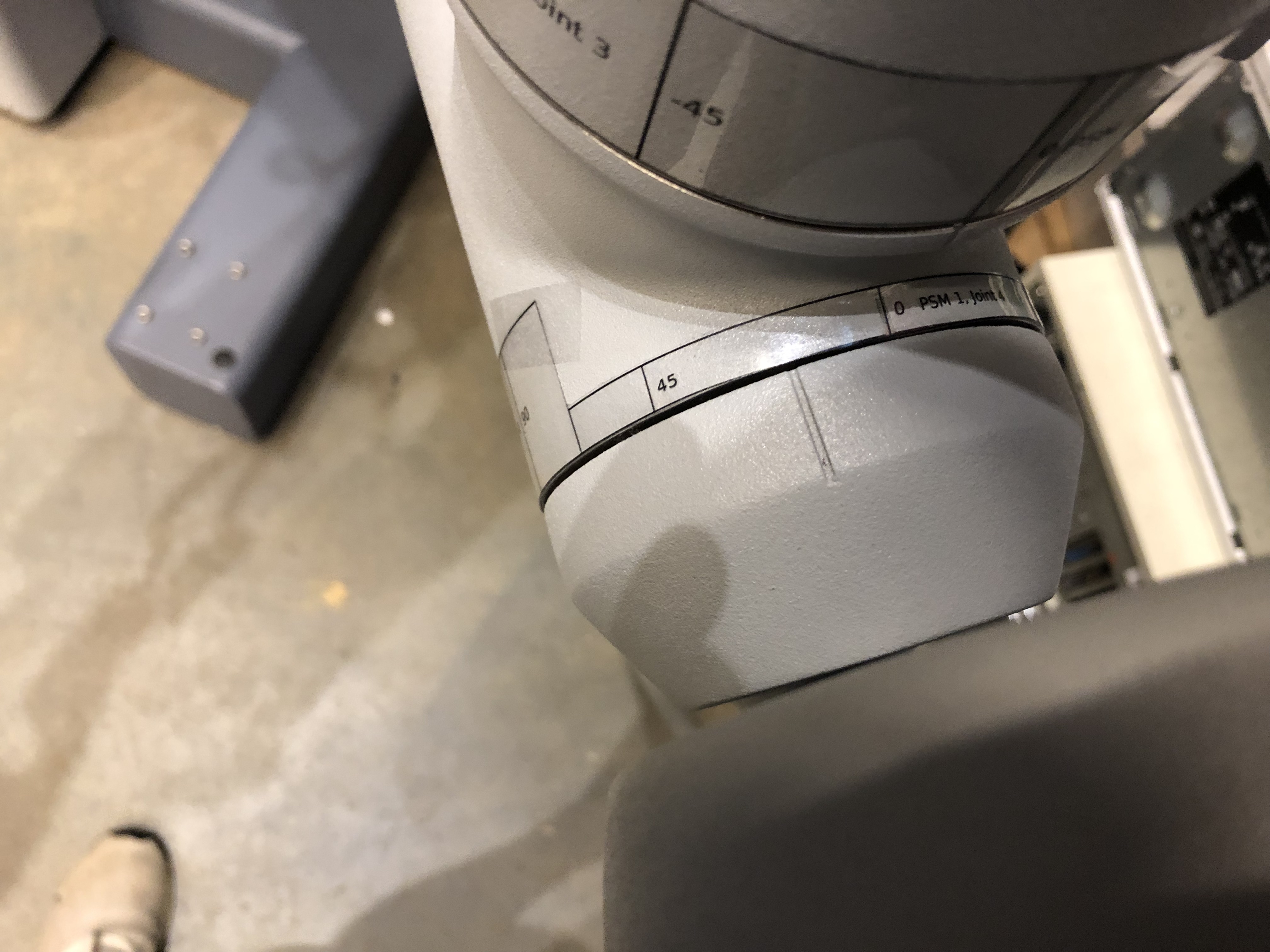
Every joint moves in the positive direction when turned counter-clockwise and in the negative direction when turned clockwise. This is why the labels for joint 4 on the three PSMs are the only labels with negative values on the left and negative values on the right.
Make sure to put the labels on the link before the joint.
PSM1 and PSM2 have identical SUJs except for their second joints that have the same geometry but have different bounds of rotation (PSM1 moves from -135 to 0 and PSM 2 moves from 0 to 135). This is why the directions for their label placement is the same.
Warning
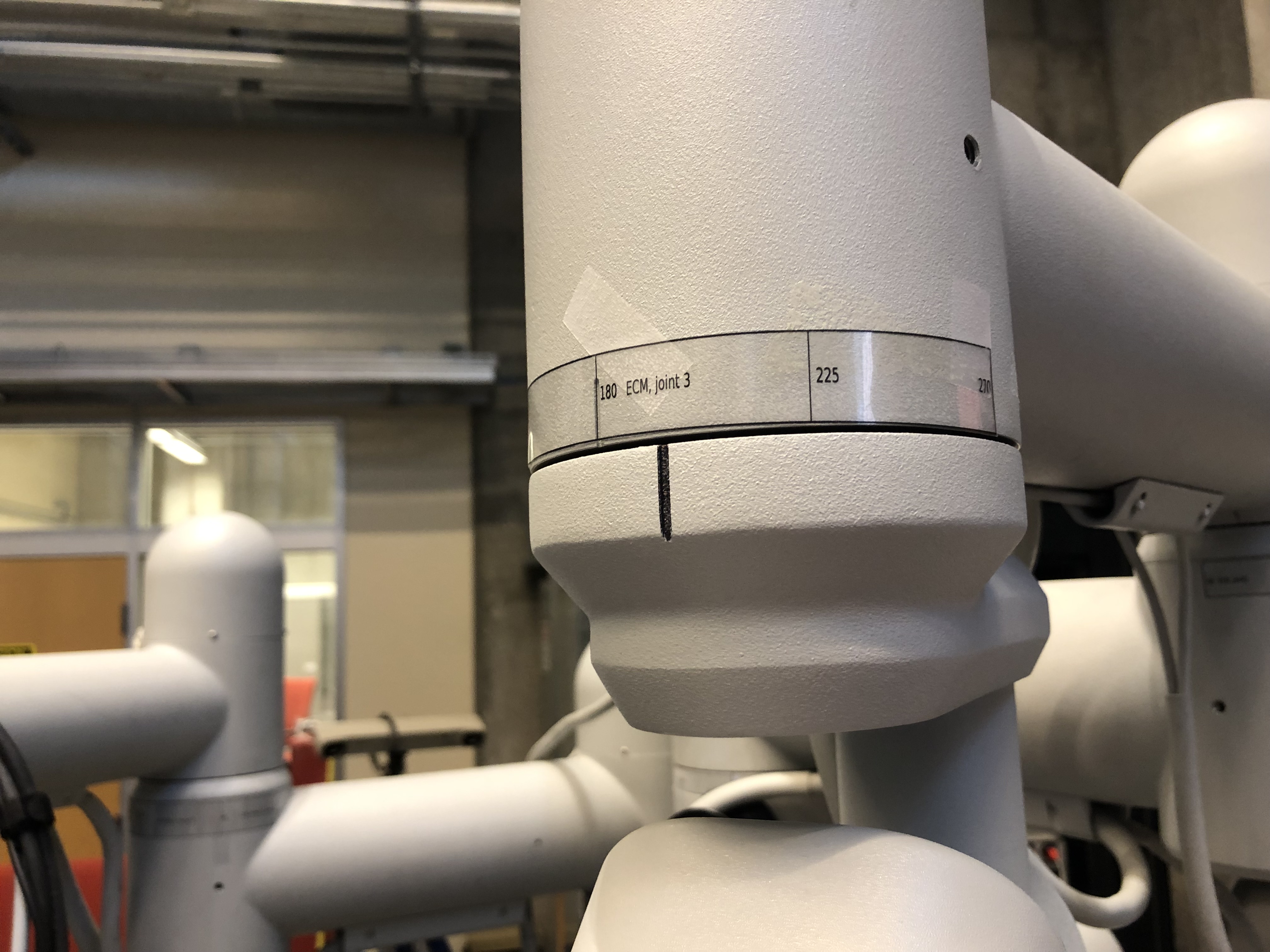
The label for joint 3 of the ECM is made so that 180 is the value that is aligned with the divot in the joint because the 0 position for the ECM is where the ECM is facing the support column.
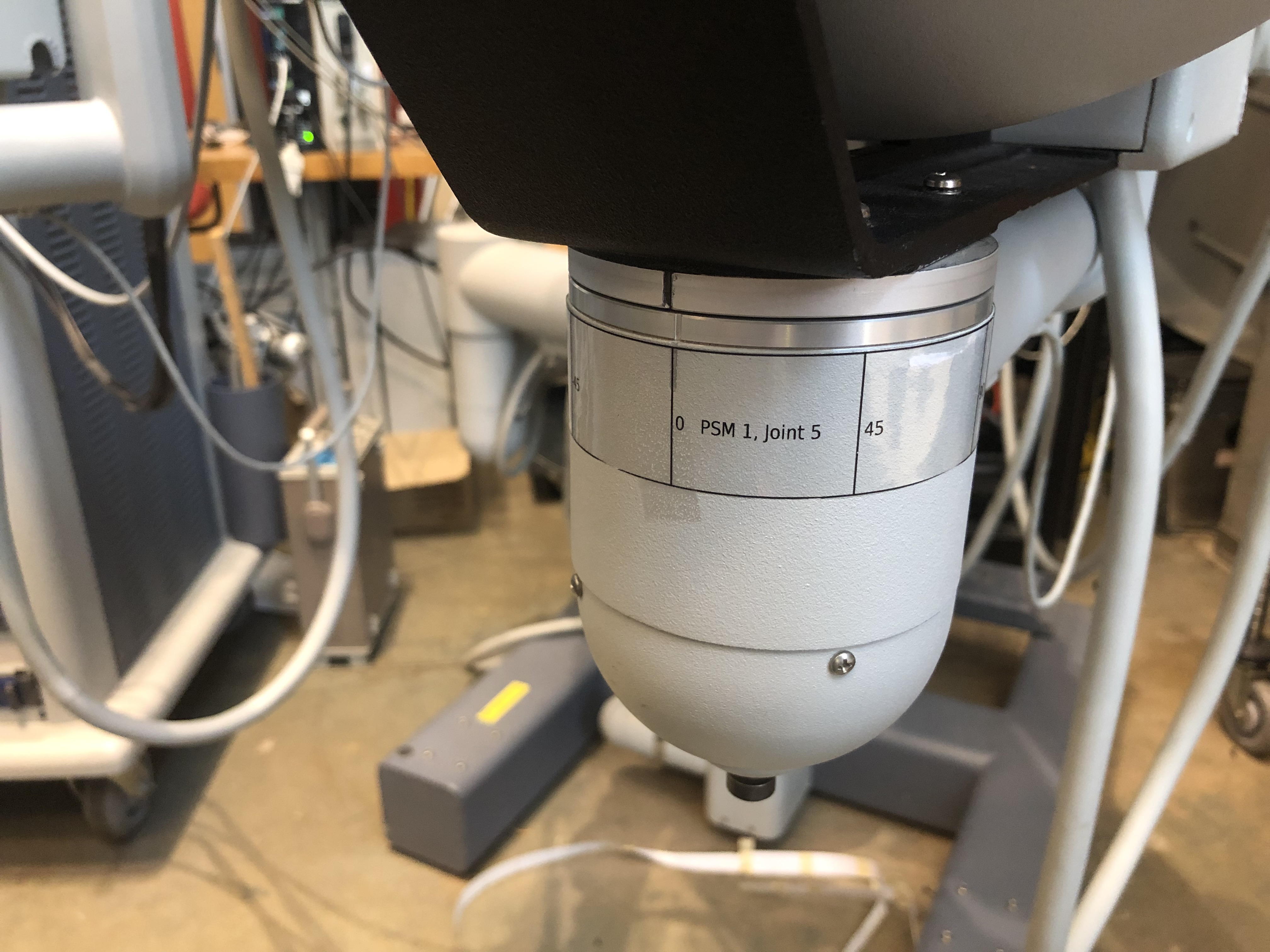
PSM1 and PSM2
All images are “clickable” for full resolution. Label positions on PSM1 and PSM2 for joints 1 to 5.
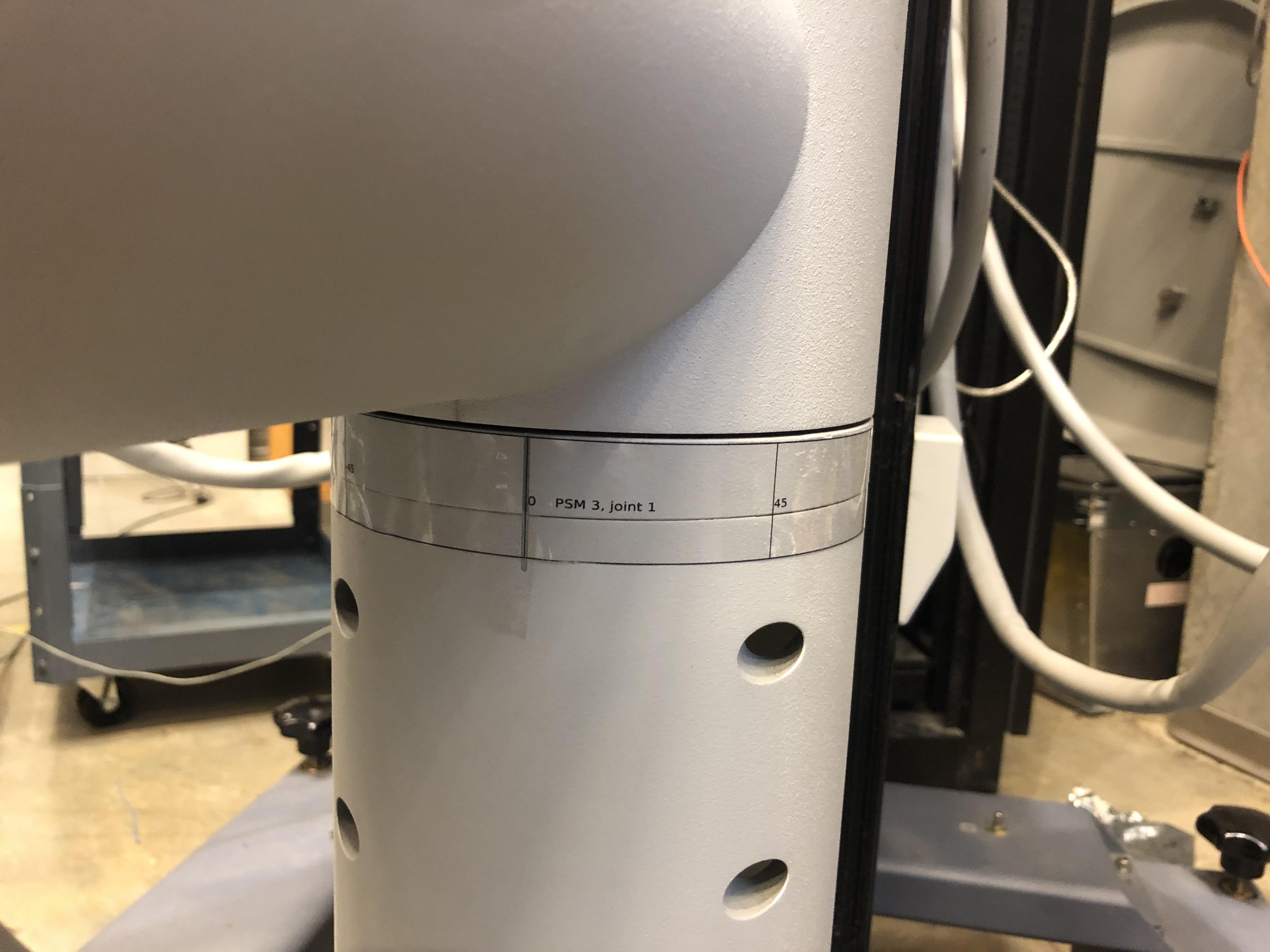
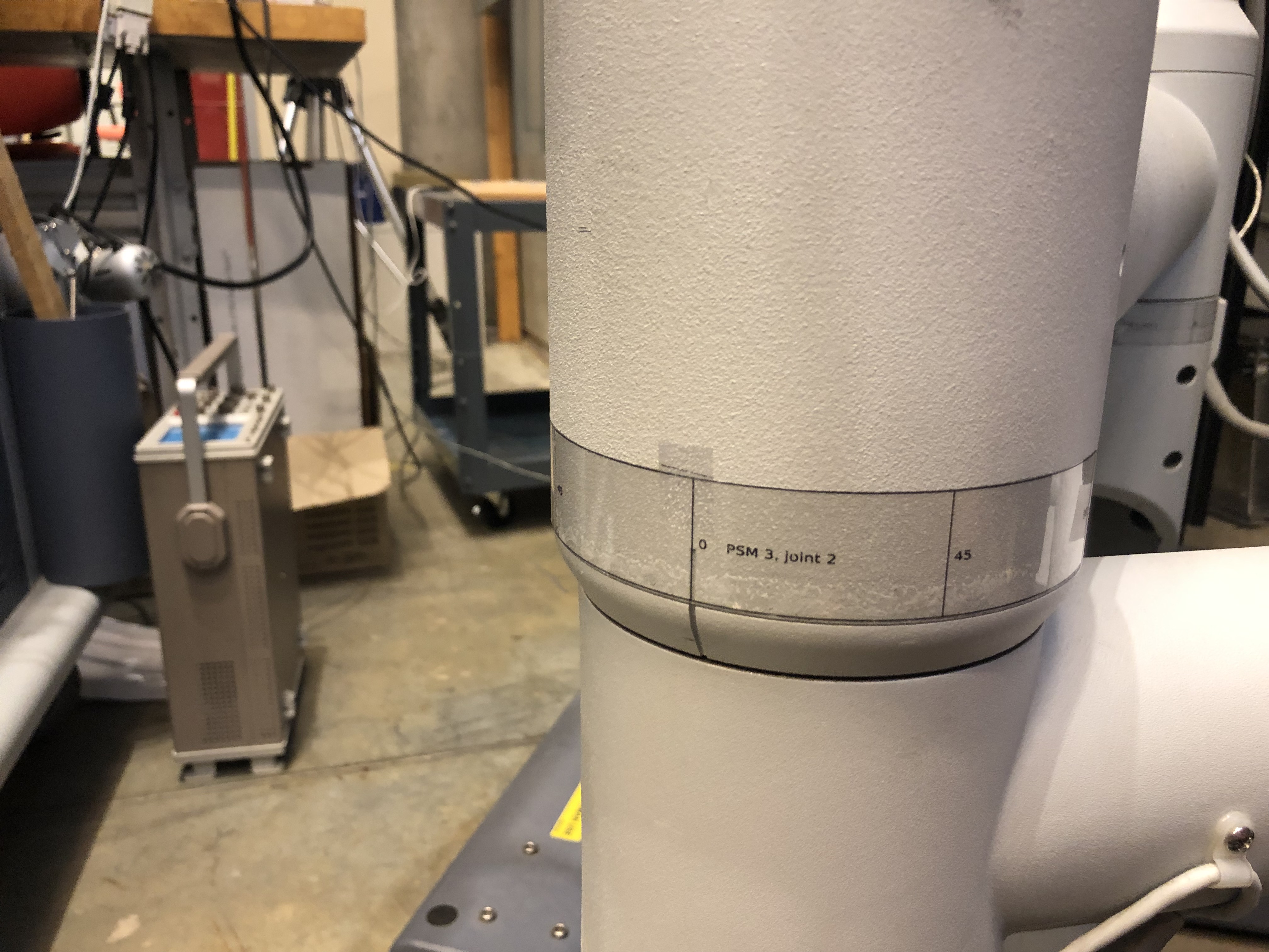
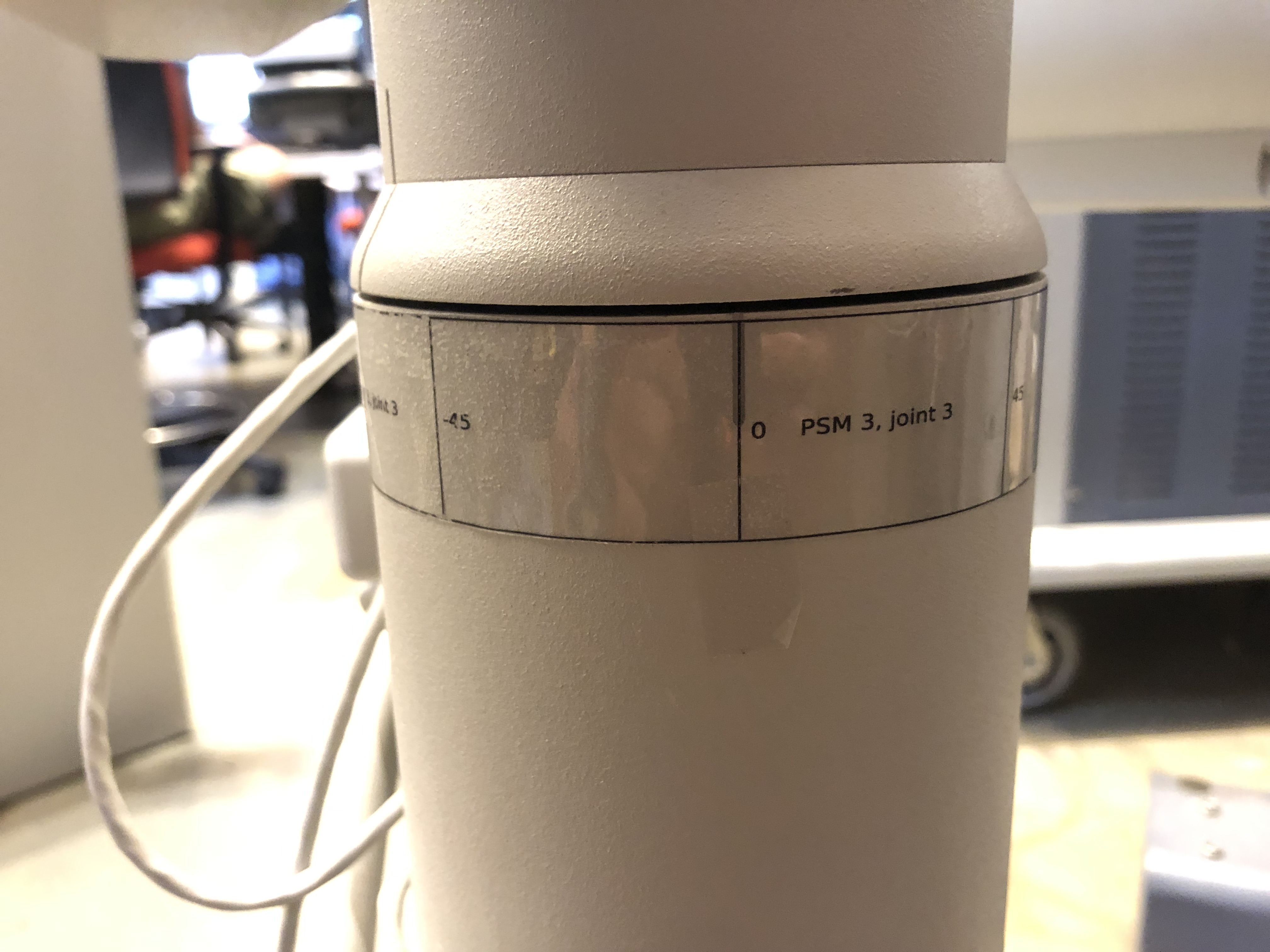
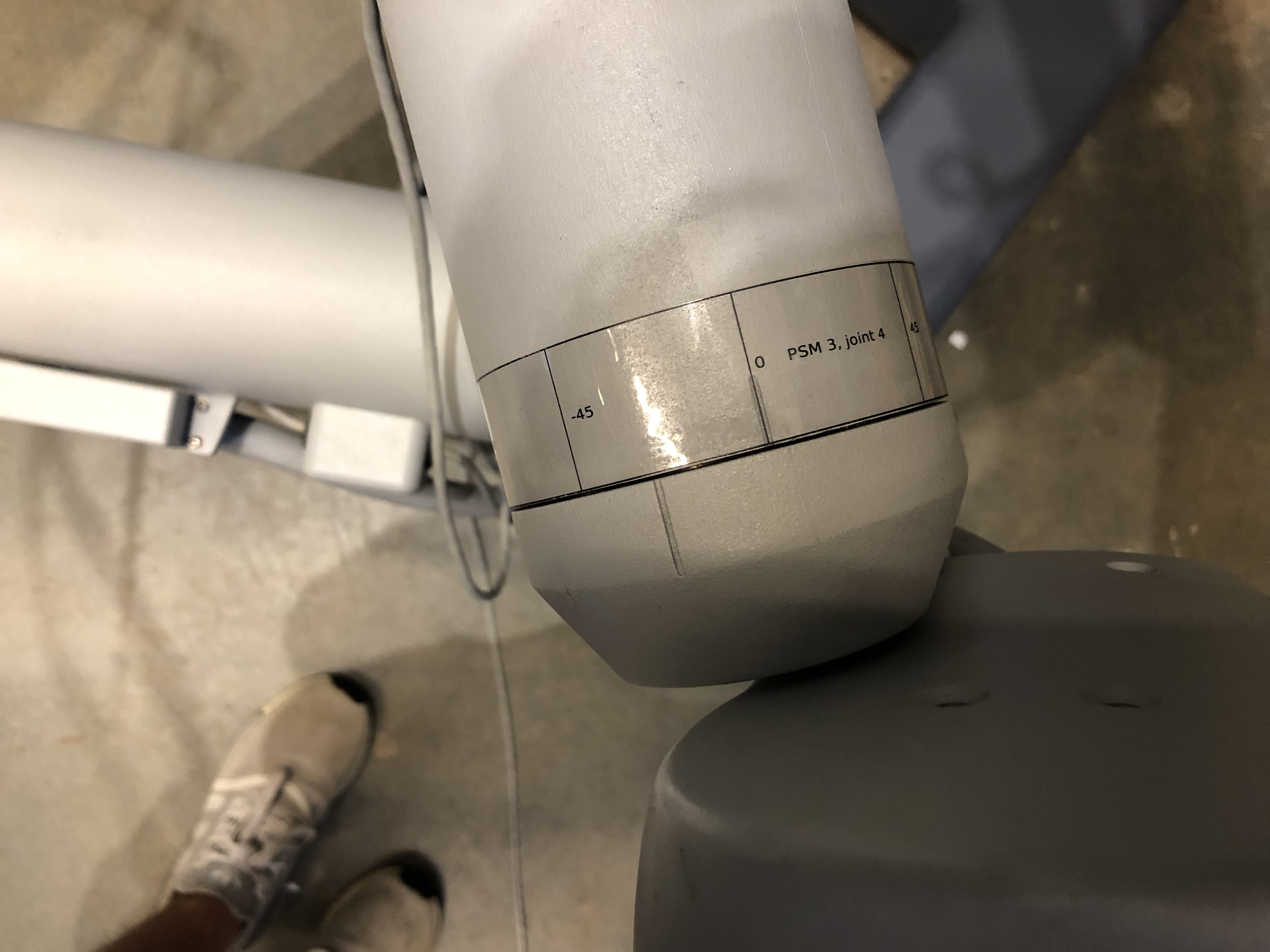
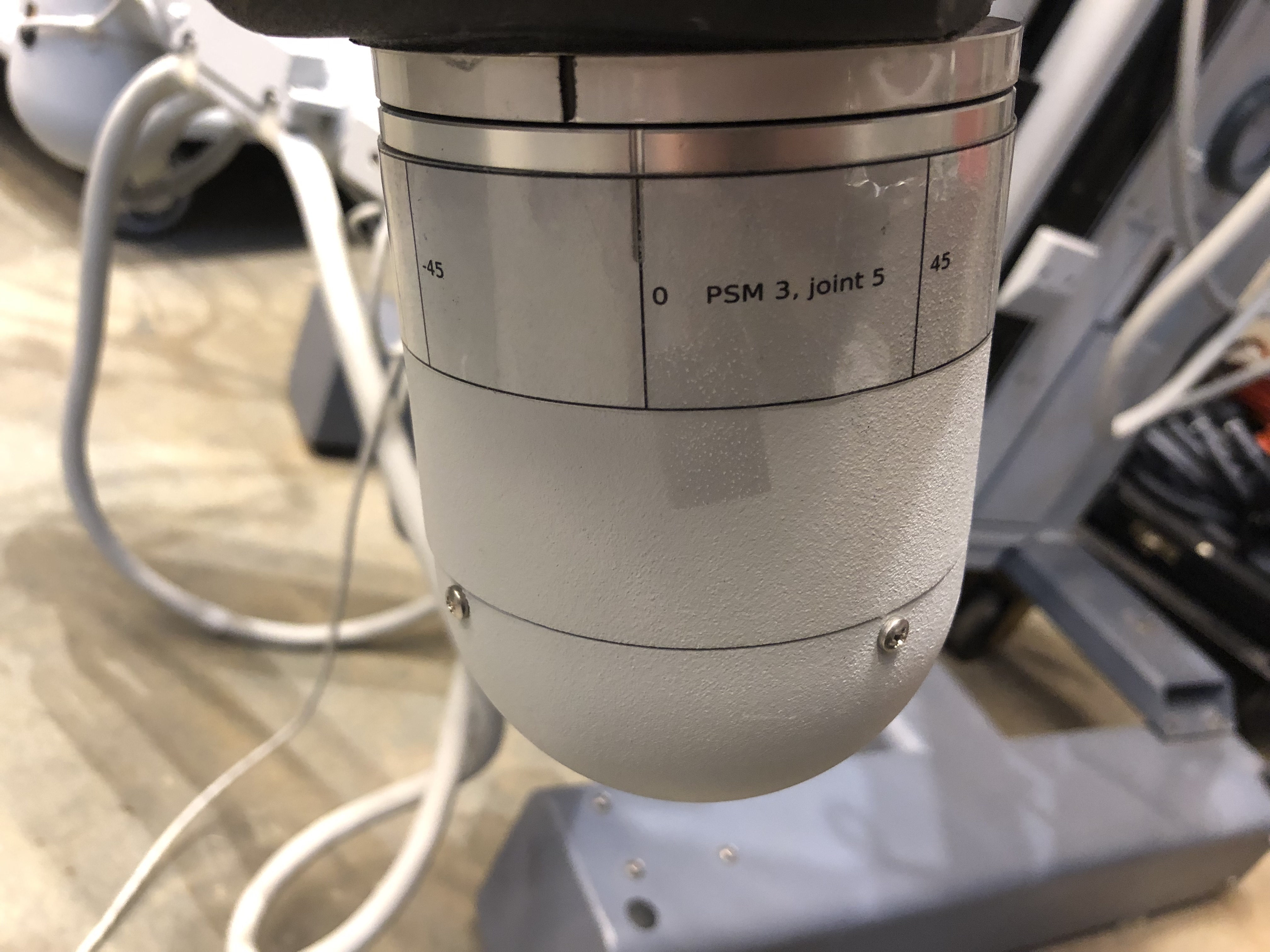
PSM3
Label positions on PSM3 for joints 1 to 5.
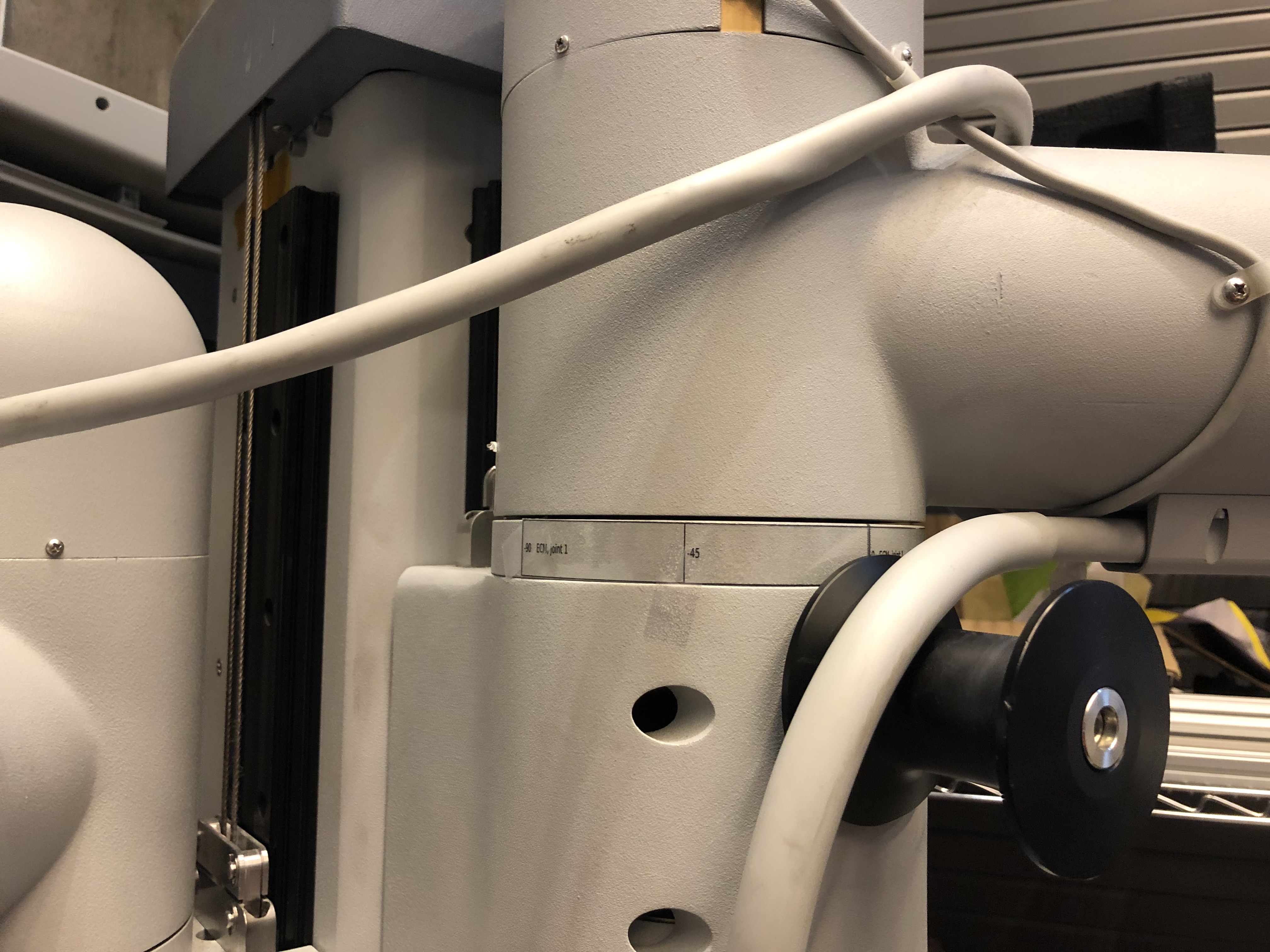
ECM
For the ECM, make sure the label for the 3rd joint is positioned so 180 is on the divot.
Label positions on ECM for joints 1 to 3.

8.1.8.3. Calibration
Overview
When you’re using the dVRK SUJ controller, the joint values are measured using potentiometers. The voltage measured has to be converted to an angle using a simple linear transformation. Since each system has different potentiometers, each system need to be individually calibrated. To do so, the dVRK GUI provides a very simple interface that allows to compute the scale and offset for the linear transformation using two set points. At each point, the controller will provide the voltage and the user has to provide the measured angle using some kind of external measurement tool.
For all the rotational joints, we found that the labels provide a reasonable estimate. For the translation joints, we don’t currently have a good system. The process described here relies on a cheap laser measurement tool (or a measuring tape).
The main steps to perform the calibration for one SUJ are:
Position the joints one by one (it’s easier if you’re in a small space)
Release the brakes (you might need a helper to press the GUI “Clutch” button in the arm SUJ tab)
Position the arm to one extreme of the joint space, at a position with a reading on the labels you attached to the joint
Re-engage the brakes
Wait a few seconds for the position to be measured by the dVRK controller (we rely on potentiometers and a multiplexer. It takes time to cycle through all 24 potentiometers)
Enter the joint position you read on the label in the GUI “Joint Start” (click on the “Show more” button to see the calibration widget). By default, the position is set to -inf. When you enter the actual joint position, the application records the current potentiometer value
On the same joint, go to the other extreme position and enter the real joint position in “Joint Finish”. The point of using 2 positions as far as possible to each other is to minimize the error when we’re computing the slope for the potentiometer to position linear function. “Joint Start” and “Joint Finish” can be in any order, i.e. that start joint value doesn’t have to be smaller than the joint finish value.
Repeat for all 6 joints on your SUJ. If you’re calibrating the ECM SUJ, enter bogus values for the last two joints. Just make sure these values are all different.
Once you’ve entered all the joint positions needed (i.e. 4x2 for ECM SUJ, 6x2 for PSM SUJs), hit the “Manual Recalibration” button.
The manual recalibration is a simple line fit for each pair of positions. The result will be printed in your terminal, you have to manually copy/paste the new values to your SUJ configuration file (e.g.
suj-ECM-1-2-3.json). The output should look like:SUJ scales and offsets for arm: Timestamp (auto): 0.14189 (valid) Value: PSM3 Please update your suj.json file using these values "primary-offsets": [ 2329.7, -59930, 1.9507e+05, -2.6861e+05, -2.3586e+05, -3.0817e+05], "primary-scales": [ -5461.2, 98040, -57190, 98040, 1.0558e+05, 1.3726e+05], "secondary-offsets": [ -23431, 28095, -2.0391e+05, 1.8798e+05, 1.9171e+05, 2.1985e+05], "secondary-scales": [ 17476, -45752, 59677, -68628, -85785, -98040], When you copy/paste these values to your configuration file, make sure you're modifying the section for the SUJ you're currently calibrating.
When you’re done calibrating all SUJs, quit the dVRK console application and restart it to test the calibration.
PSM1 and PSM2
The calibration table in the SUJ GUI has two rows and six columns. The first column is for joint 0, second for joint 1, third for joint 2, and so on.
Joint 0
To calibrate joint 0 it is necessary to have a laser measuring tool (a measuring tape will do in a pinch).
Lower the PSM to its lowest point.
Place the measuring tool underneath joint 1 as shown in the picture below.
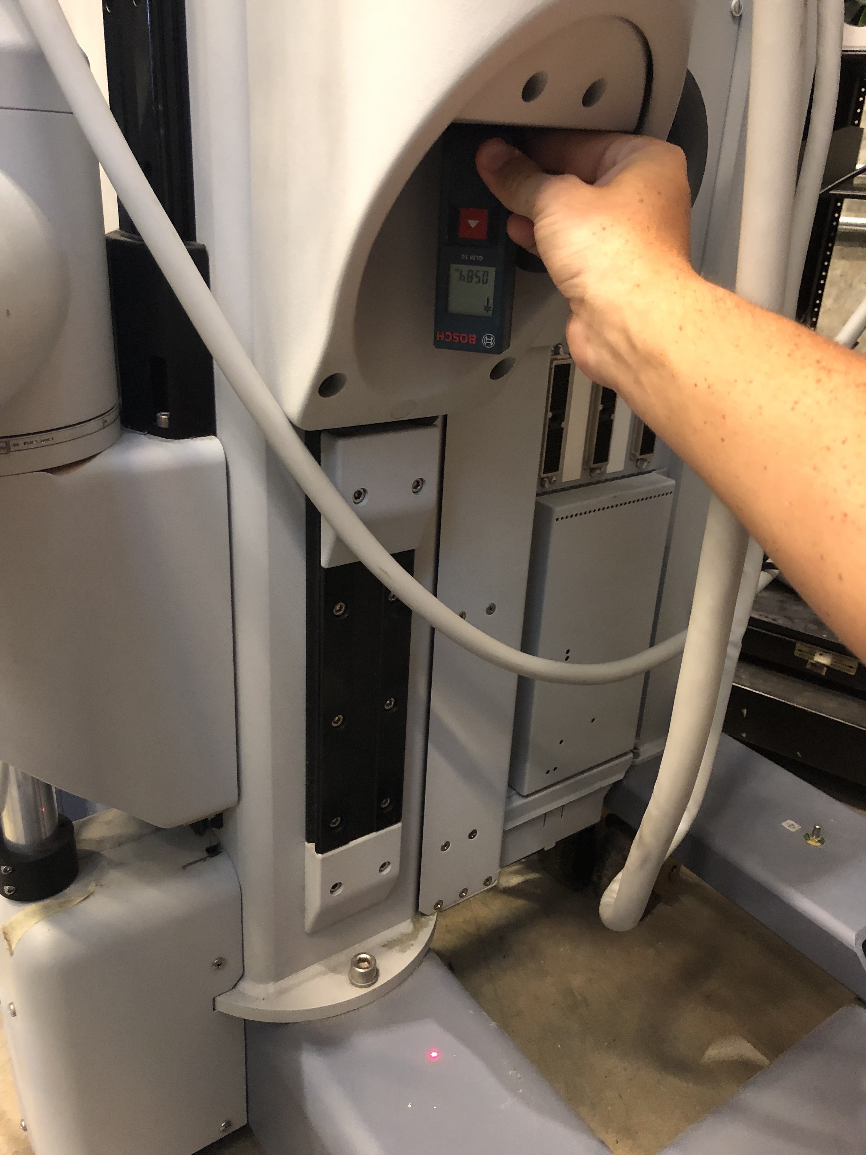
Find and record the height of the PSM.
Enter 0 in the graphical table in the first column of the first row.
Raise the PSM to its highest point.
Find and record the height of the PSM.
Subtract the final height from the initial height.
Enter the difference in height in the second column of the first row.
Joints 1-5
Turn the joint to an extreme (either its highest or lowest degree measurement on the label).
Enter that angle into the graphical table in the first row and in the column that corresponds with the joint.
Turn the joint to the other extreme.
Enter that angle into the graphical table in the second row and in the column that corresponds with the joint.
Repeat until all 5 joints have values in the top and bottom row.
PSM3
Joint 0
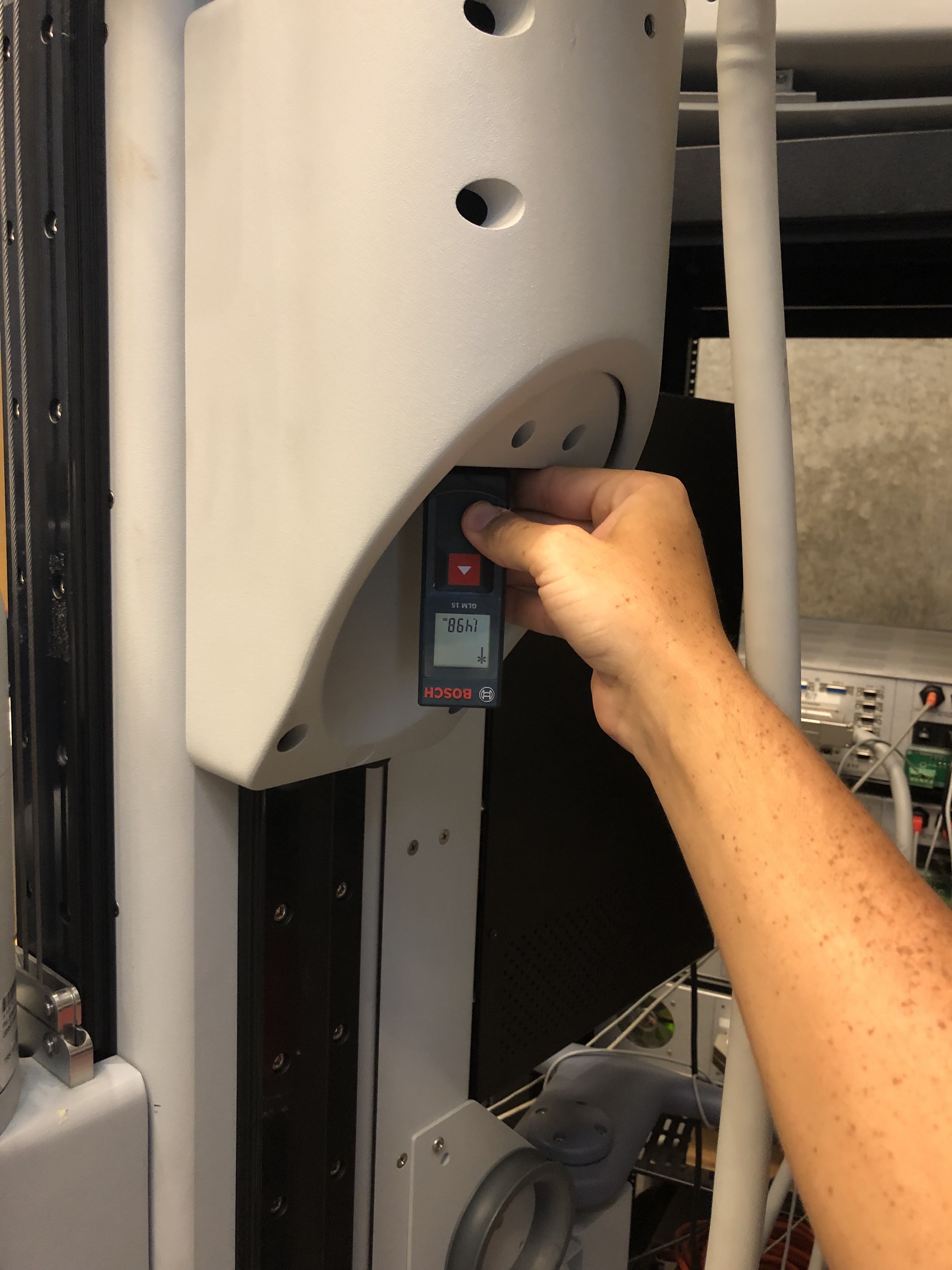
To calibrate joint 0 it is necessary to have a laser measuring tool.
Lower the PSM to its lowest point.
Place the measuring tool underneath joint 1 as shown in the picture below of PSM1 (all 3 PSMs have similar flat pieces under their joints).
Find and record the height of the PSM.
Enter 0 in the graphical table in the first column of the first row.
Raise the PSM to its highest point.
Find and record the height of the PSM.
Subtract the final height from the initial height.
Enter the difference in height in the second column of the first row.
Joints 1-5
Turn the joint to an extreme (either its highest or lowest degree measurement on the label).
Enter that angle into the graphical table in the first row and in the column that corresponds with the joint.
Turn the joint to the other extreme.
Enter that angle into the graphical table in the second row and in the column that corresponds with the joint.
Repeat until all 5 joints have values in the top and bottom row.
ECM
The ECM can only be calibrated after calibrating PSM1 or PSM2
Joint 0
Lower the ECM to its lowest point.
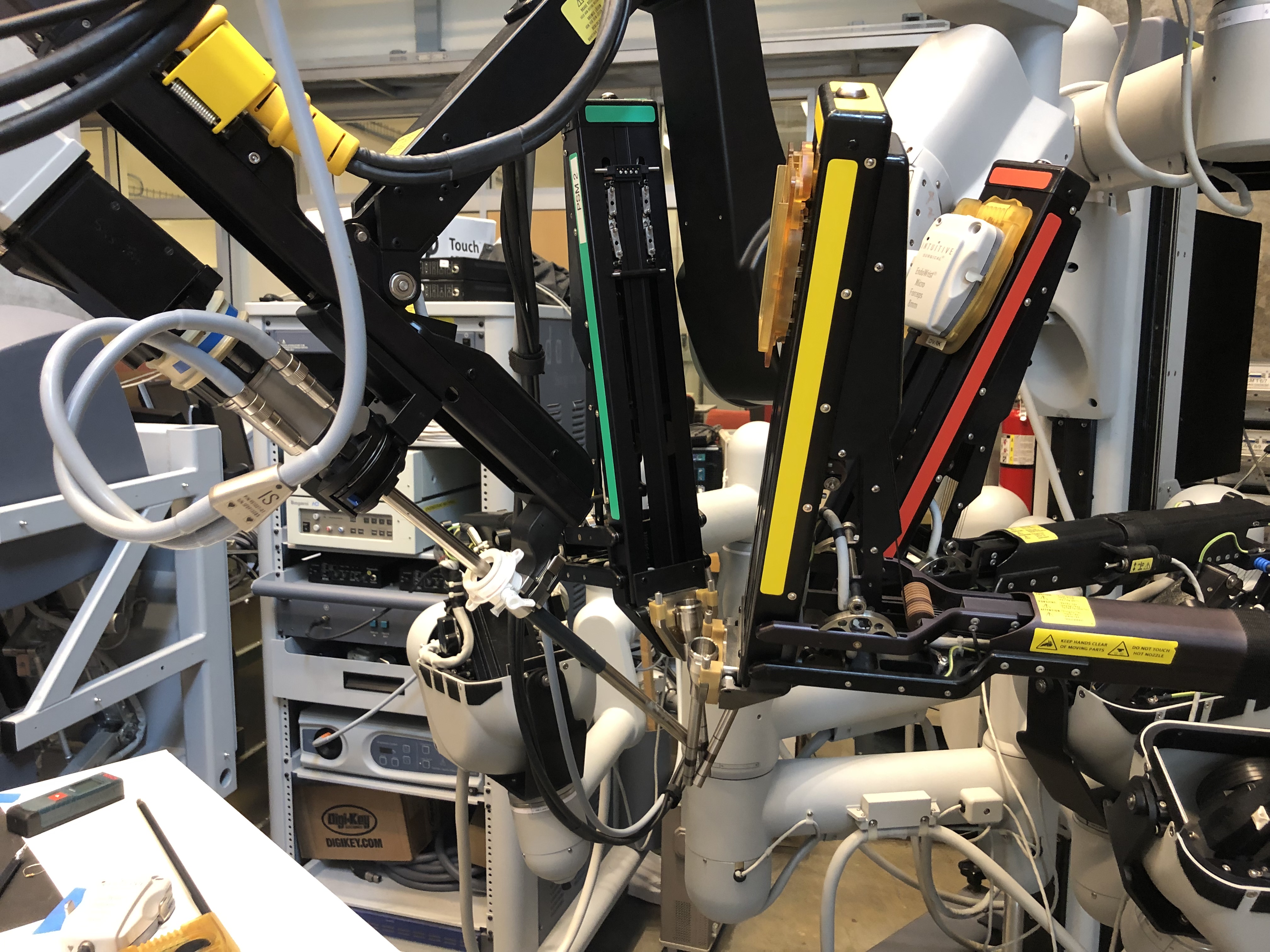
Lower PSM1 to the point at which the bottom of PSM1’s second joint and the ECM’s second joint are level as seen below.
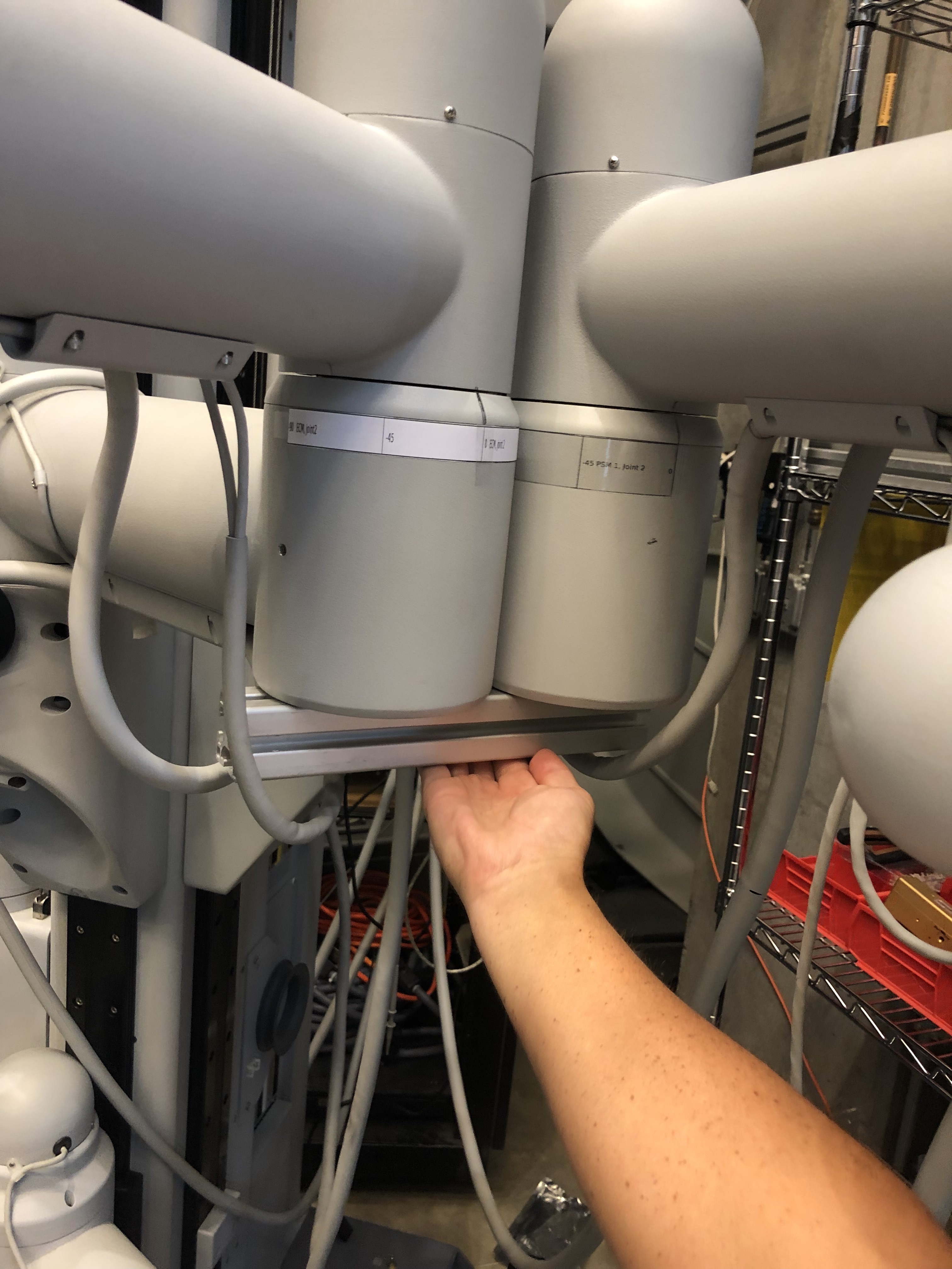
Enter 0 in the graphical table in the first column of the first row.
Raise the ECM to its highest point.
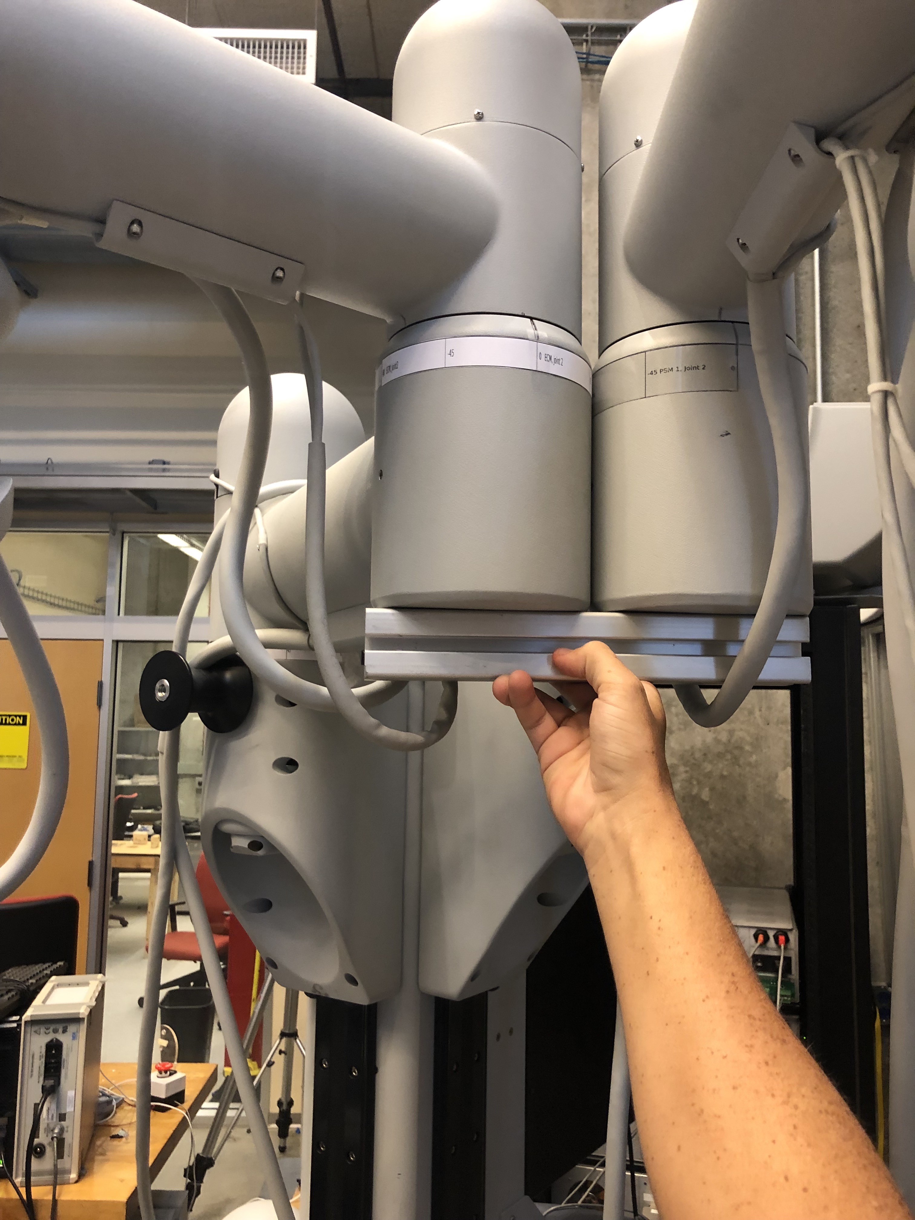
Raise PSM1 to the point at which the bottom of PSM1’s second joint and the ECM’s second joint are level as seen below.
Subtract the final height from the initial height.
Enter the difference in height in the second column of the first row.
Joints 1-3
Turn the joint to an extreme (either its highest or lowest degree measurement on the label).
Enter that angle into the graphical table in the first row and in the column that corresponds with the joint.
Turn the joint to the other extreme.
Enter that angle into the graphical table in the second row and in the column that corresponds with the joint.
Repeat until all 3 joints have values in the top and bottom row.
Fill the last two columns in with random numbers as place holders.
When the table is full of values hit “Manual Calibration” and the correct offsets and scales will print in the terminal.
8.1.8.4. Validation
When the calibration is complete, release the SUJ brakes and place all the RCMs together. Then check that the reported position of each SUJ arm (e.g. SUJ PSM1, SUJ PSM2…) in the GUI are within a 20 mm cube of each other. The RCM point is the large black stripe on the cannulas.
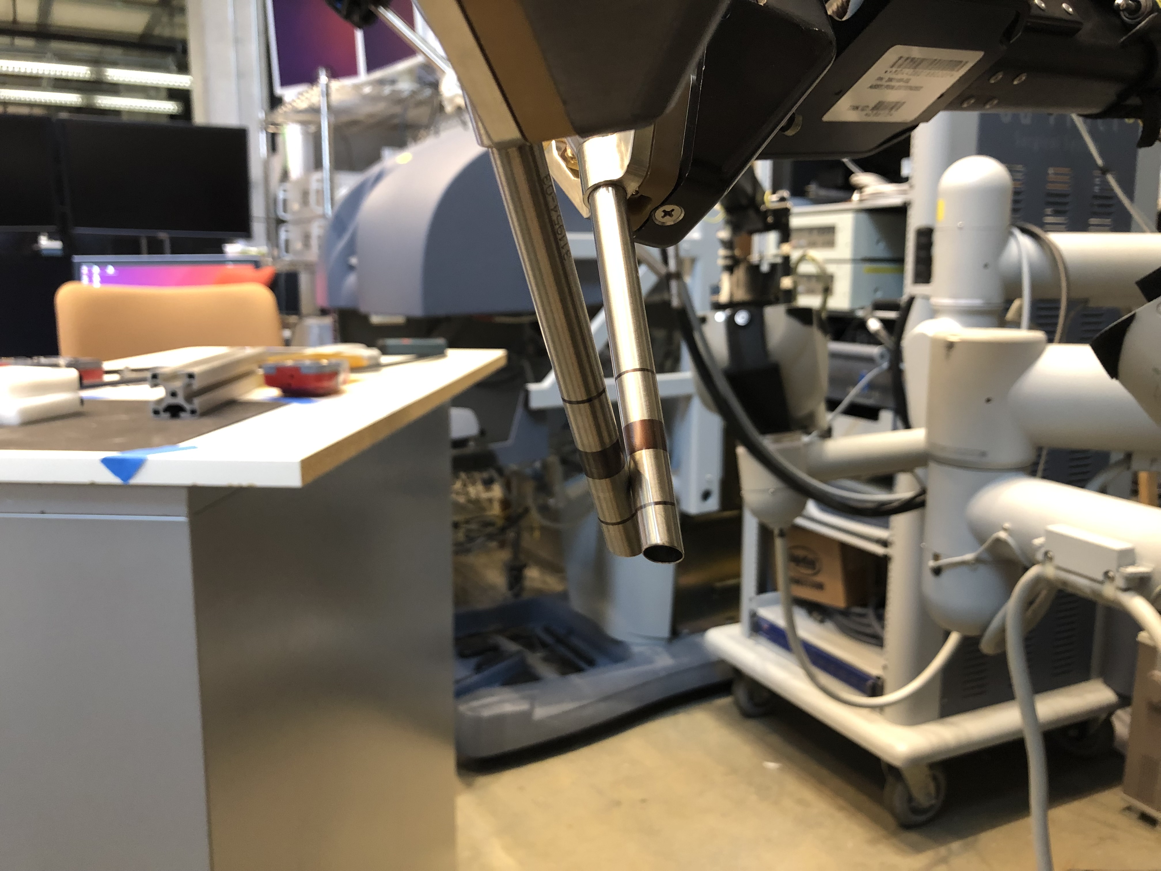
RCM points positioned close to each other
The positions reported in the arm widgets (PSM1, PSM2…) should also show fairly short distance with respect to the ECM. To make sure your setup joints are properly calibrated, repeat the same experiment in different locations. Move the ECM first and then position each PSM so their RCM is as close as possible to the endoscope tip.
RCM points positioned close the endoscope tip (origin)