
2.2.1.2. Logic board FPGA
Introduction
Overview
The “logic” board, also known as “FPGA” board is used to process and pass data between the robotic arm and the computer.
On the computer’s side, all FPGA boards have two FireWire ports so dVRK controllers can be daisy-chained with the PC. Generation two introduces an Ethernet port per logic board. V2 boards can directly communicate with a PC. They can also be used to bridge between a FireWire chain of controllers and a PC over Ethernet (see connectivity). All versions of FPGA boards (from 2012 on) are supported by the latest dVRK firmware and software. All FPGA boards are uniquely identified on the FireWire or Ethernet chain by their board ID.
On the robotic arm’s side, all FPGA boards are mounted on top of a “power” board (QLA, QLA via DQLA or dRAC). The connection is made through standoff connectors placed under the FPGA board. All versions of the FPGA boards use the same layout for the connection to the “power” board to ensure backward compatibility.
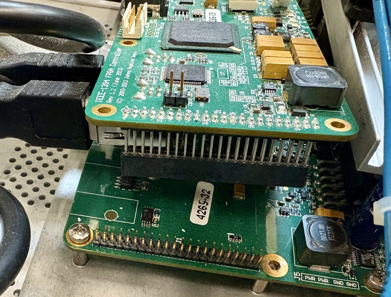
FPGA V1 ready to install on QLA (note internal black FireWire cables)
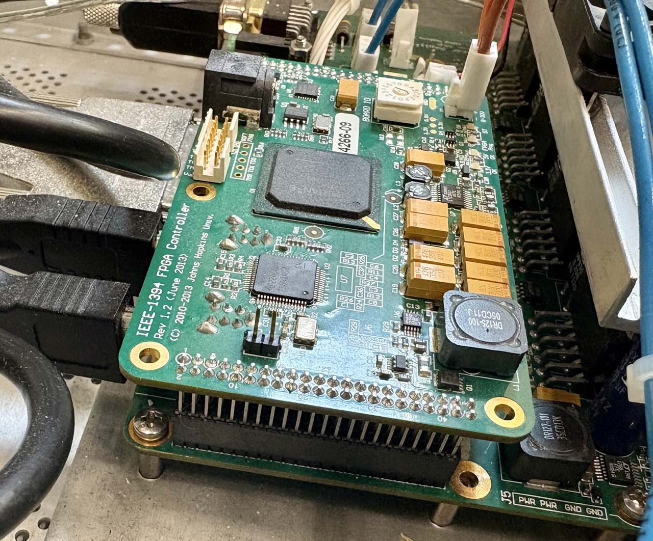
FPGA V1 mated to QLA
The FPGA boards send requested motor power to the “power” board, i.e. either QLA (da Vinci Classic) or dRAC (da Vinci Si). The requested motor power can be either current or voltage (for recent dVRK controllers). The logic board also receives signals from the robot through the “power” board. For example, the QLA power boards have both specialized chips for encoder reading and analog to digital converters (ADC) to read the potentiometer and Hall effect sensors. The dRAC power board doesn’t need to convert signals coming from the arm since these arms contain their own conversion board, ESPM (Electronic Serializer for Patient Manipulator). The ESPM board comes from Intuitive, but the firmware is specific to the dVRK. It uses a custom communication protocol to send data (encoders, potentiometers…) to the dVRK-Si controllers.
V3 specificities
The FPGA V3 also adds a dual-core ARM 32 processor embedded on the same chip as the FPGA. This arm processor can run Linux along with some user code while having fast access to the FPGA data. We plan to take advantage of this feature for embedded computing (e.g. PID) and fast data collection. See also embedded mechatronics.
The FPGA V3 has a SD card slot used to:
Load the FPGA chip’s firmware
Boot the ARM processors
Store user data
The FPGA V3 has significantly more I/Os and gates than the FPGA V1/V2 therefore they are able to manage more than one QLA board at a time. To use a single logic board with 2 QLA, we introduced a set of boards to bridge two QLAs to a single FPGA. We call this board set DQLA.
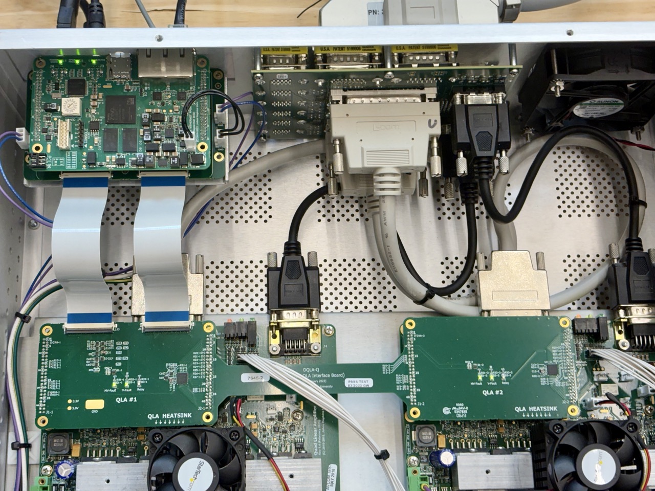
DQLA set of boards and flat cables between the 2 QLAs (bottom left and right) and the FPGA (top right)
Finally, with the FPGA V3, all new dVRK controllers are designed so the logic board is installed against the side of the controllers so all the ports (Ethernet, FireWire, SD card) can be accessed without internal pass-through cables.

FPGA V3 against the back of DQLA controller
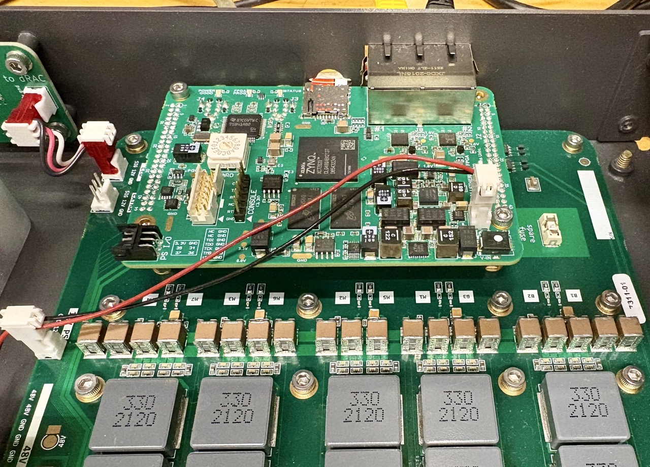
FPGA V3 against front of dRAC controller
Details
Main versions of logic boards and core features:
FPGA V1 (https://github.com/jhu-cisst/FPGA1394)
until to 2015
based on FPGA Xilinx Spartan 6
two FireWire ports for daisy-chaining
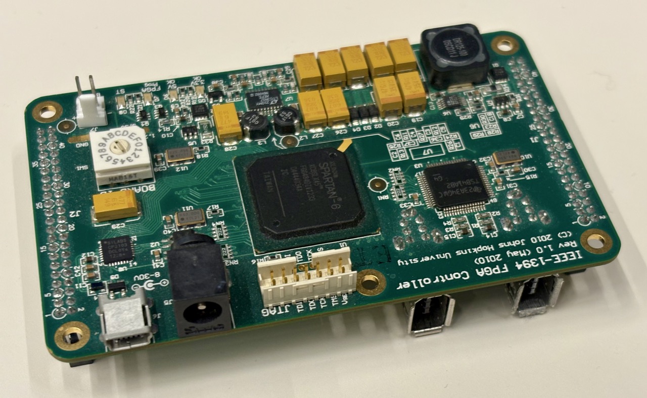
FPGA V1 top view
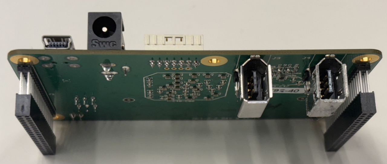
FPGA V1 bottom view
FPGA V2 (https://github.com/jhu-cisst/FPGA1394)
from 2016 to 2023
based on FPGA Xilinx Spartan 6
added one Ethernet port (100MB)
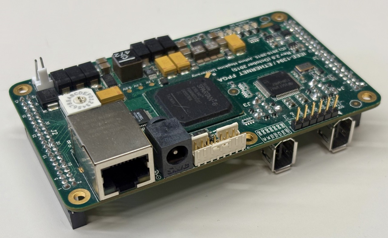
FPGA V2 top view
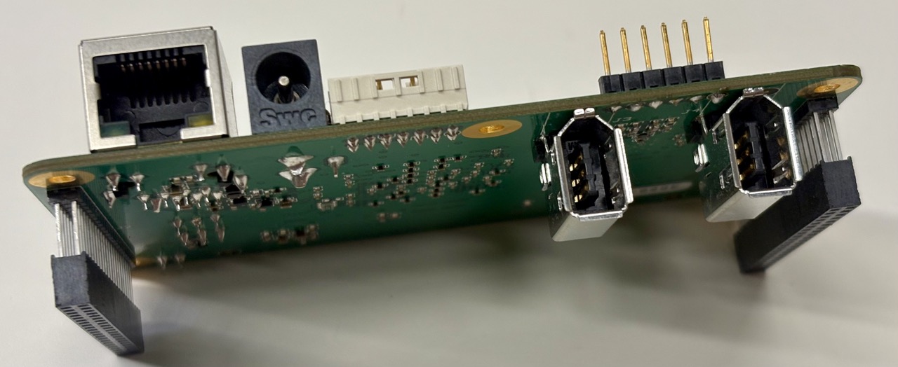
FPGA V2 bottom view
FPGA V3 (https://github.com/jhu-cisst/FPGA1394V3)
from 2023
based on Xilinx Zynq System on Chip (SoC), XC7Z020
embedded dual-core ARM 32 processor
added another Ethernet port (two ports, 1GB)
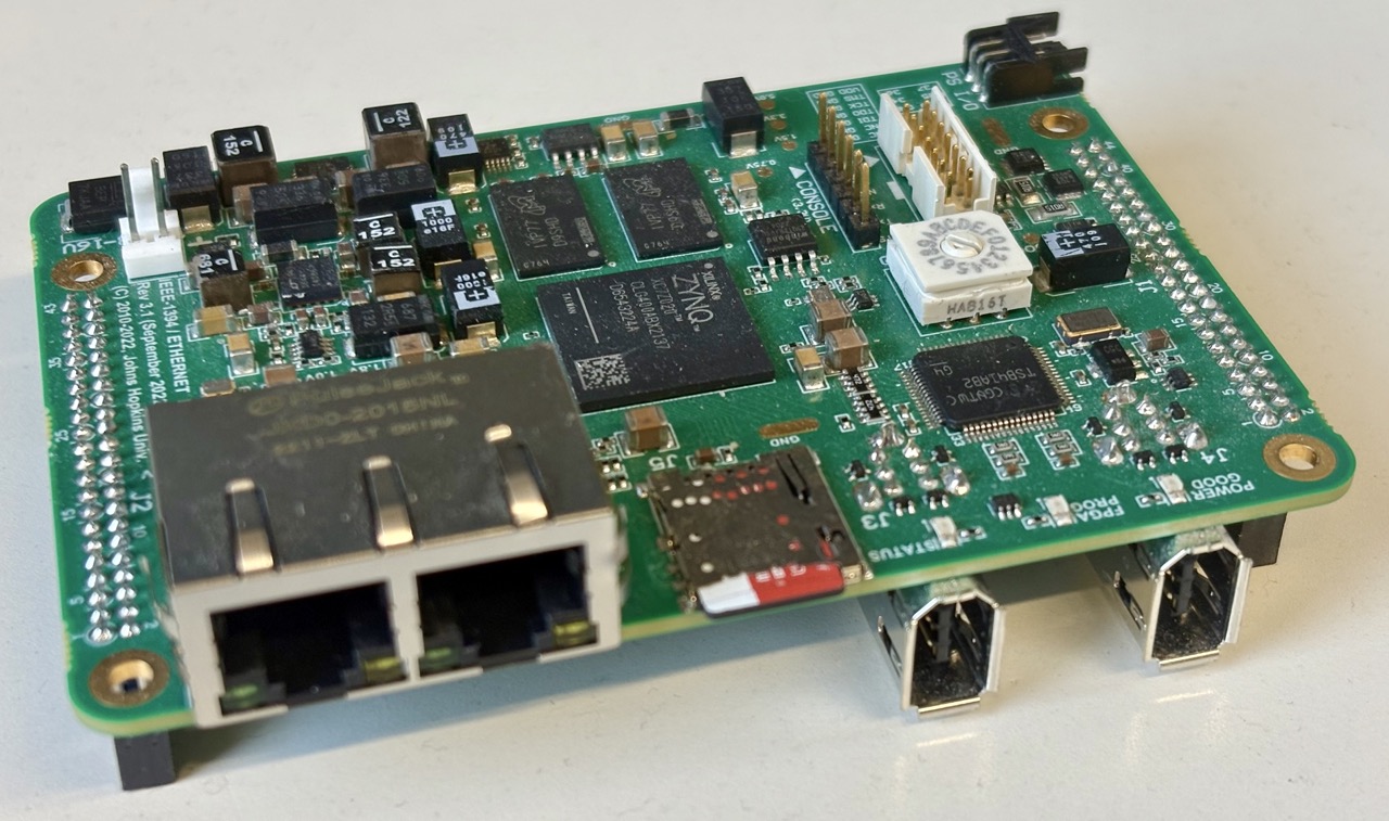
FPGA V3 top view
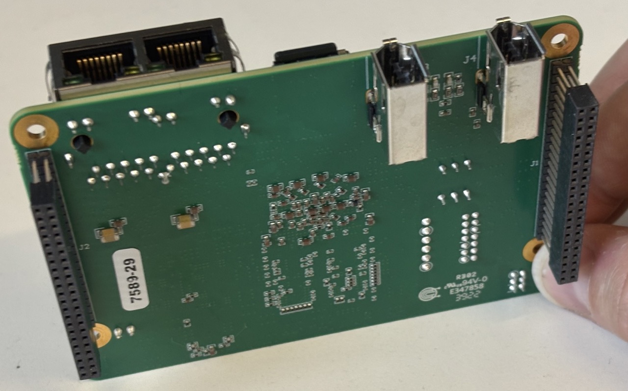
FPGA V3 bottom view
See also the controller versions page to determine which FPGA version is used.
Number of FPGAs
The number of FPGAs (and therefore number of FireWire or Ethernet nodes) depends on the controllers versions and the number of arms. The dVRK Classic controllers with FPGA V1 or V2 each have two logic boards (aka QLA1). The dVRK Classic controllers with FPGA V3 (DQLA), the Classic SUJ controllers (QLA1) and dVRK-Si controllers (dRA1) all use a single logic board. There is no dVRK-specific FPGA board used for the Si SUJ.
In practice:
The initial dVRK kits were composed of two PSMs and two MTMs. We used 4 dVRK Classic controllers so a total of 8 dVRK FPGAs.
For a full first generation da Vinci with the dVRK controllers V1 or V2, we have two MTMs, one ECM, three PSMs and the SUJ. So six arm controllers using 12 logic boards and one more for the Classic SUJ controller for a grand total of 13 FPGAs.
More recent controllers use less FPGA boards so a full Si patient cart with two Classic MTMs require only 6 FPGAs.
Note
The expected number of boards is useful when testing your physical connections.