
2.2.4.2. Exterior
Connectors
One AC power connector, with on/off switch
D-sub for data (LVDS)
D-sub for motors and brakes power
Two FireWire connectors
Two Ethernet connectors
4 and 5-pin safety chain connectors; see E-Stop
One SD card slot for the firmware and user applications controllers
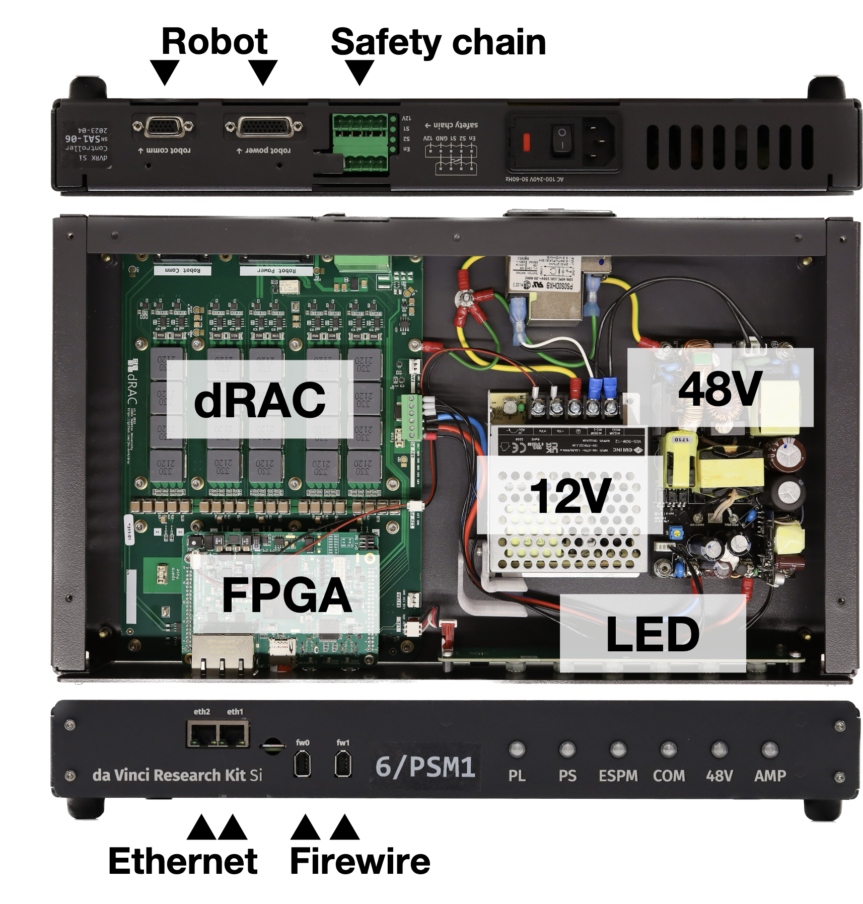
dVRK-Si controller
LEDs
The dVRK Si controller has 6 LEDs on the front panel. During the boot sequence, the six LEDs blink green from left to right. While the LEDs are blinking, the controller searches which firmware file should be used on the SD card based on the underlying hardware (dRAC vs DQLA).
Once the firmware is found and started:
PL: indicates the state of the FPGA, blinking green when normal
PS: indicates the state of the embedded OS (not used)
ESPM: indicates if the ESPM is correctly connected to the controller, solid green when normal
COM: not used
48V: main motor power is enabled, green when powered
AMP: state of the axis amplifiers. Off if all the motor amplifiers are off, solid green if any amplifier is on. The LED will blink red if the controller has to shutdown (e.g. communication watchdog timeout)
The LEDs on the back of the controller are directly mounted on the FPGA logic board.