7.1.3. ECM brakes
7.1.3.1. Introduction
Note
Make sure you use an ECM controller, i.e. a controller with a single 36V motor power supply for both FPGA-QLA sets. Controllers for the MTMs have two power supplies for the motors, a 24V for the first 4 axes and a 12V for the last 4 axis. Controllers for the PSMs have a single power supply for all axis, but it is only 24V. On your controller, set the board IDs to 4 and 5 (see board Ids). As for the PSMs, you must connect the cable that comes directly from the arm to the controller.
Note
The Si ECM and PSMs also have brakes on the first 3 joints. There seems to be very little variations between the different arms, the values provided by default (generated by dvrk-config-generator.py) should work for most systems. Users will likely not need to calibrate their brakes.
The Classic ECM differs from the Classic PSMs, it requires brakes to remain in place. The PSMs are designed with counterweights so if they loose power, they can fall on or in the patient. The ECM holds a fairly heavy endoscope, so brakes are required to prevent unwanted motion. Note that the first 3 joints have brakes but not the 4th (roll along the endoscope).
There are 4 important values that will need to be tweaked to control the 3 ECM brakes. These are hardware specific and therefore store in the ECM IO XML configuration file.
ReleaseCurrent: current required to release the brakes - the “Unit” field in the XML file is not read by the software, replacing it bymAwon’t have any effect so make sure to specify theValuein amperesReleaseTime: amount of time you need to keep the current high to release the brakes (in seconds)ReleasedCurrent: current required to maintain the brakes released. This value should be significantly lower than the current to initially release the brakesEngagedCurrent: current required to engage (lock) the brakes. On the ECM, always zero.
There is no automated calibration process, so users have to manually edit values in the XML file. In the generated configuration file, pay attention to the section “AnalogBrake” and the default values.
<AnalogBrake AxisID="0" BoardID="5">
   <AmpsToBits Offset="32819" Scale="5242.88"/>
   <BitsToFeedbackAmps Offset="-6.25" Scale="0.000190738"/>
   <MaxCurrent Unit="A" Value="0.300"/>
   <ReleaseCurrent Unit="A" Value="0.300"/>
   <ReleaseTime Value="2.000"/>
   <ReleasedCurrent Unit="A" Value="0.080"/>
   <EngagedCurrent Unit="A" Value="0.000"/>
</AnalogBrake>

ECM Classic brake current
Please note that the values provided on this page are hardware specific, and you must adjust them to your system. Ideally, you want to find the lowest possible current that still work reliably on your hardware.
Warning
You really need to perform this step. We have no sensor to detect if the brakes are released or not. This means that the system will assume the brakes are released and then apply motor current. Even though the arm might still be blocked by the brakes, the PID controllers can apply a fair amount of current and damage the motors.
7.1.3.2. Procedure
Warning
If you haven’t done it yet, remember to calibrate the brakes
current feedback (with -b
command line option).
At that point, we don’t have a utility program to automatically adjust the parameters specific to the brakes, namely the 4 following values in the XML file:
ReleaseCurrentandReleaseTimeReleasedCurrentEngagedCurrent, though this one is easy, it should be set to 0.Warning
Based on specification sheets that we believe correspond to the solenoid used for the 3rd brake (insertion) on the Classic and S/Si ECMs, we should not exceed 13W for 7 seconds or 1.3W for continuous drive. That would translate to 1.48A for the
ReleaseCurrentand 0.465A for theReleasedCurrent.
For this procedure we will use the sawRobotIO1394QtConsole program along with the ECM XML configuration file for your arm. You will need to manually edit the XML file and between changes, quit and restart the sawRobotIO1394 console program to test the new values.
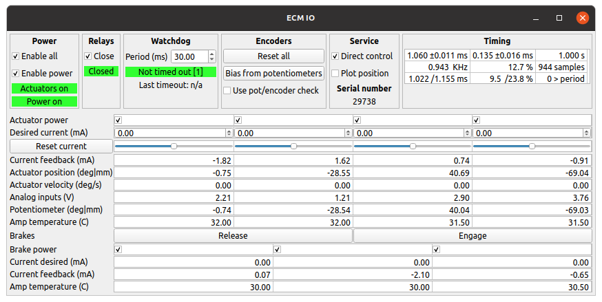
sawRobotIO console for an ECM
The first step is to determine the
ReleaseCurrent.In the XML file, set all the
ReleasedCurrent(NOTE: releaseD current) to zero and theReleaseTimeto 10 seconds. Start from a low value for theReleaseCurrentfor all 3 brakes. values (~0.1 for 100 mA).Start the sawRobotIO1394 console and click Enable All to power the actuators and brakes.
Press the Release button for the brakes. You should see the requested current move to the value set in the XML file and a current feedback close to it. After 10 seconds (or whatever
ReleaseTimeyou’ve set in the XML file), current should go back toReleasedCurrentvalue (i.e. 0 for now).During these 10 seconds, try to move the ECM, joint by joint. If you stand close to the arm, you should even hear a click if the brakes get released.
If a given brake is not released, quit the application, increase the value of
ReleaseCurrent(andMaximumCurrentif needed) for the corresponding joint in the XML file and try again.You can increase the requested current to an extent, i.e. the hardware is limited by the power supply so make sure you always check the current feedback. If the current feedback doesn’t increase as you’re increasing the requested current (and software maximum current), it means that you have reached the maximum possible with your power supply.
Once you’ve found the proper values for
ReleaseCurrent, you can decrease theReleaseTimevalue, ideally all the way down to 2.0 seconds.The last step is to find the lowest possible for
ReleasedCurrent. This is the current appliedReleaseTimeseconds afterReleaseCurrentto keep the brakes from re-engaging. It’s IMPORTANT to find the lowest possible value. Again, start from a low value and increase progressively until you find settings such that the brakes stay released.
We are not totally sure how much variability there is between systems. In order to get a sense for it, please update the following table after you calibrated your brakes:
System |
1 Release (A) |
1 Release (s) |
1 Released (A) |
2 Release(A) |
2 Release (s) |
2 Released (A) |
3 Release(A) |
3 Release (s) |
3 Released (A) |
|---|---|---|---|---|---|---|---|---|---|
JHU |
0.250 |
2.0 |
0.090 |
0.220 |
2.0 |
0.090 |
1.100 |
2.0 |
0.200 |
ISI |
0.250 |
2.0 |
0.100 |
0.210 |
2.0 |
0.100 |
1.200 |
2.0 |
0.200 |
WSU |
0.270 |
0.5 |
0.120 |
0.300 |
0.5 |
0.130 |
1.100 |
2.0 |
0.170 |
UCL |
0.250 |
2.0 |
0.040 |
0.140 |
2.0 |
0.040 |
1.100 |
2.0 |
0.200 |
PU |
0.250 |
2.0 |
0.130 |
0.180 |
2.0 |
0.100 |
1.100 |
2.0 |
0.200 |
VU-MP |
0.250 |
2.0 |
0.080 |
0.220 |
2.0 |
0.070 |
0.800 |
2.0 |
0.200 |
Note
Older dVRK controllers
We found that the power requirements are close to the maximum amount of power a 24V power supply initially installed can deliver. There is some variability between different systems and brakes so you might need to upgrade the power supply to 36V in the controller enclosure. To check if you have reached the maximum deliverable power, keep an eye on the current feedback. These values should be close to the required current. If the current feedback seems to plateau while you increase the requested current, you’ll likely need to upgrade your power supply.