
12.1. Potentiometers
12.1.1. Introduction
Warning
This page is for the first generation da Vinci arms (aka Classic, Standard). If you have Si arms (ECM, PSM), this page is irrelevant.
The dVRK uses the analog potentiometers on the robotic arms to:
Home the arms. The encoders are relative encoders so we use the potentiometers to find and pre-load the zero value. See potentiometer calibration
Perform safety checks. Once the arms are powered, the dVRK software continuously monitors the joint (or actuator based on each type of arm) positions reported by both the encoders and the potentiometers.
For the safety checks, we use two different parameters per potentiometer. Consistency is based on:
Distance, i.e. error tolerated in position between both readings (
abs(pots - encoders))Latency, i.e. amount of time during which the distance is continuously above a given threshold
The challenge is to find the “best” distance and latency for each system.
Important notes regarding the MTMs:
The last motorized joint (7), i.e. the roll has a potentiometer but the dVRK doesn’t use it, neither for homing nor for safety checks. To avoid errors we simply set a very high Distance threshold. In Rev 1.6 and above, the value 0.0 should be used to simply disable the safety check. Please ignore the reported analog position for this axis.
The very last “joint” (8), i.e. the gripper doesn’t have an encoder. The dVRK only uses the analog input of the 8th axis (no encoder, no motor). The analog input is the value from the Hall effect sensor in the MTM gripper. As for the 7th axis, we set a very high Distance threshold to avoid errors. In Rev 1.6 and above, the value 0.0 should be used to simply disable the safety check. Please ignore the reported encoder joint and actuator positions as well as velocities.
12.1.2. Connections
If you’re running into error messages regarding potentiometer and encoder inconsistencies, the first thing to check is the physical connections. Potentiometers feedback is an analog signal and is sensitive to bad connections/grounding. You will need to check the following connections:
The large Cannon ITT connector at the back of the dVRK controller (see Cannon ITT. Make sure the connector is clean and the screw on the back is tighten (a quarter turn).
The two Micro DB68 SCSI cables between the dMIB and the QLA boards (see dVRK related acronym definitions).
To help yourself locate these connectors, check the dVRK Classic controller’s documentation
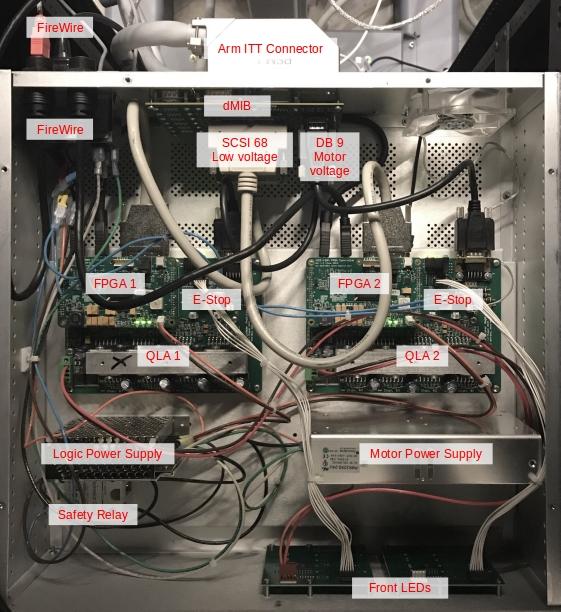
QLA1 based controllers
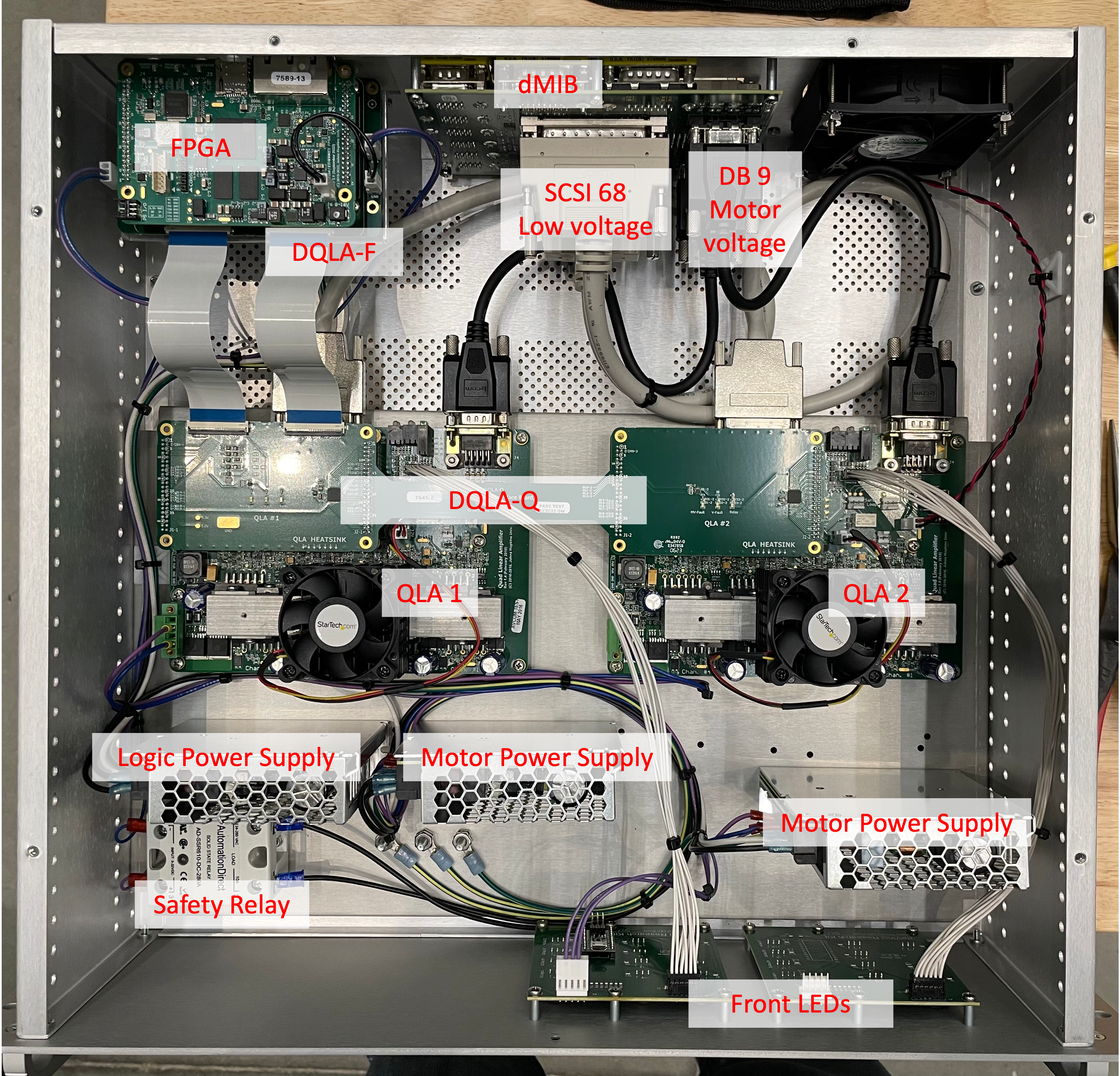
DQLA based controllers
For each connection (i.e. ITT connector and both ends of the DB68 cable):
Clean the connectors, we recommend both compressed air (canned) and contact cleaner (e.g. WD Contact Cleaner). You should clean both the cable ends and the connectors on the PCBs
Make sure all screws are tight
12.1.3. Visual checks
It is possible that one of the encoders or the potentiometers is defective. The easiest way to check this is to use the graphical user interface and control the robot using the IO widget.
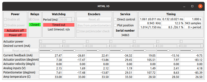
IO widget, text view
Start the system application and configure the system without homing:
Do not hit Power On nor Home buttons. If you have, just hit Power Off
Select the IO tab corresponding to your arm
In the IO tab, check Direct control and approve
If you just started the system application and the arm hasn’t been moved, both Joint position and Actuator position rows should be close to zero
The Potentiometer values will be oscillating but should be fairly stable (e.g. a few tenths of degrees/millimeters)
Then click Bias from potentiometers. This step will pre-load the encoders based on the potentiometers
The box Use pot/encoder check should be unchecked
At that point, you will need to move the arm by hand. If you’re using a PSM or ECM, remove any tool, sterile adapter or endoscope to make it easier to back drive the arm.
Note
If you’re using an ECM, make sure you have someone helping you who can Release and Engage the brakes using the graphical user interface. Someone must be holding the ECM when the brakes are released so it won’t fall down.
For each joint:
Move the joint to a physical limit (e.g. lower limit)
Check in the GUI that the Potentiometer value is close to the Joint (MTM) or Actuator value (PSM and ECM). Write down that value.
Move the joint to the other physical limit (e.g. upper limit) and check values (see step 2).
Go back to first physical limit (e.g. lower limit) and make sure you get a reading close to what you got on step 1.
If the values are not consistent within a few degrees/millimeters (these are the units used for the dVRK GUI), you likely have a broken encoder or potentiometers.
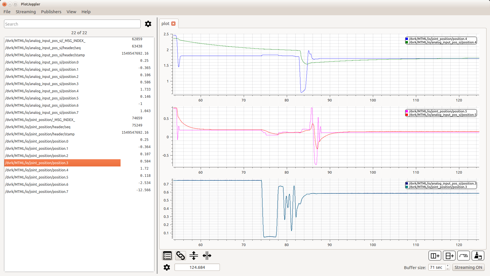
If you’re using a recent dVRK version (2.1+), there is an option to plot the encoder and potentiometer values directly in the system application. In the IO tab, under “Service”, check “Plot position”. You can then select which joint/actuator to display using the drop down menu on the left. This can be used to get a sense of what the issue is (scale, latency…).
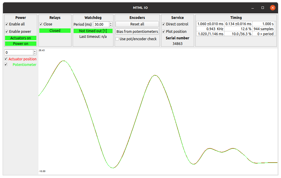
IO widget, plot view
12.1.4. Configuration files
We found that some potentiometers can be “somewhat” working so it is
possible to tweak (increase) the parameters used to trigger an error
by modifying the IO configuration file. Locate the file
sawRobotIO1394-xxx-11111.json for your arm and open it using your
preferred text editor. In that file, find the potentiometers
section:
"potentiometers": {
   "potentiometers_type": "ANALOG",
   "tolerances": [
     {
       "axis_id": 0,
       "distance": 0.08726646259971647,
       "latency": 0.01
     },
     {
       "axis_id": 1,
       "distance": 0.08726646259971647,
       "latency": 0.01
     },
     {
       "axis_id": 2,
       "distance": 0.005,
       "latency": 0.01
     }
The first parameter to increase should be the latency. The value
is given in seconds. Try to increase it progressively by doubling it
and restart the dVRK application (no need to power on/off the
controllers). If the system is still not stable, double the
latency and try again. If the system is still not stable with a
latency of 1 seconds (1.0), try the same approach with the
distance parameter.
12.1.5. Summary
Based on the plots you get for both encoder and potentiometer positions, you can determine if the issue is:
Garbage values, something is likely broken
Vertical offset or “stretch”, you should probably recalibrate your potentiometers
Horizontal offset. The potentiometer is likely too slow and you can fix this by increasing the “latency” in the JSON configuration file

Offset, need to recalibrate
Delay, likely a bad connection