3.4.3. ESPM
Note
This step is required for all PSMs and ECM Si used with the dVRK controllers, whether they are mounted on the Si SUJ or not.
3.4.3.1. Introduction
The circuit board (ESPM) inside the arm manages all the low power signals for the Si PSMs and ECMs: encoders, potentiometers, buttons, instrument Id, LEDs…
By default, it communicates with the core controller using a proprietary protocol over LVDS. JHU, in collaboration with Intuitive Surgical, developed a closed-source FPGA firmware for the ESPM that relies on an open protocol. The firmware is publicly available in a binary image only.
The ESPM programmer acts as an alternative bootloader when the arm powers-up. The dVRK specific firmware is not persistent. The arm will revert to the original firmware after a power cycle if the ESPM programmer is removed or deactivated (using switch on ESPM programmer). The ESPM programmer uses an SD card, so one can easily upgrade the dVRK firmware.
3.4.3.2. Installation
You first need to make sure the arm is not powered.
Then remove the plastic cover on the robot arm. You will need an imperial Allen wrench to remove the single bolt holding the cover. You will then need to wiggle or pry-out the cover since it’s also held by a few clips.
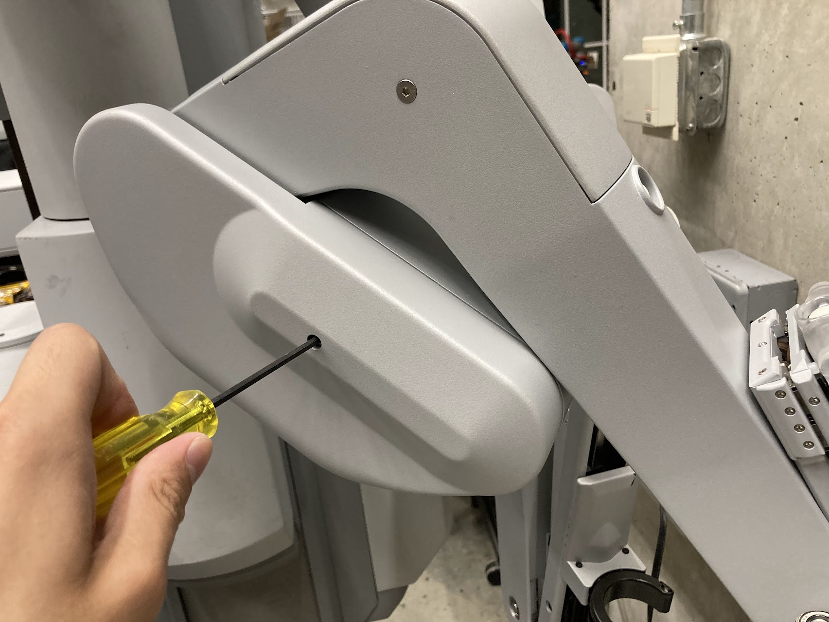
ESPM cover
Connect the ESPM programmer pigtail cable to J22 JTAG on ESPM. There are multiple identical connectors on the board. Make sure you positively identify the connector on the ESPM by the label (“J22 JTAG”) before you plug the cable in. The connector is keyed, please do not force it upside down.
Warning
The cable between the ESPM and the ESPM programmer has identical connectors on both ends but plugging it in backward will not work. If you are confused, look closely at the pictures to see which pins are populated (i.e. have a black wire crimped). You can click on the pictures to get a higher resolution view.
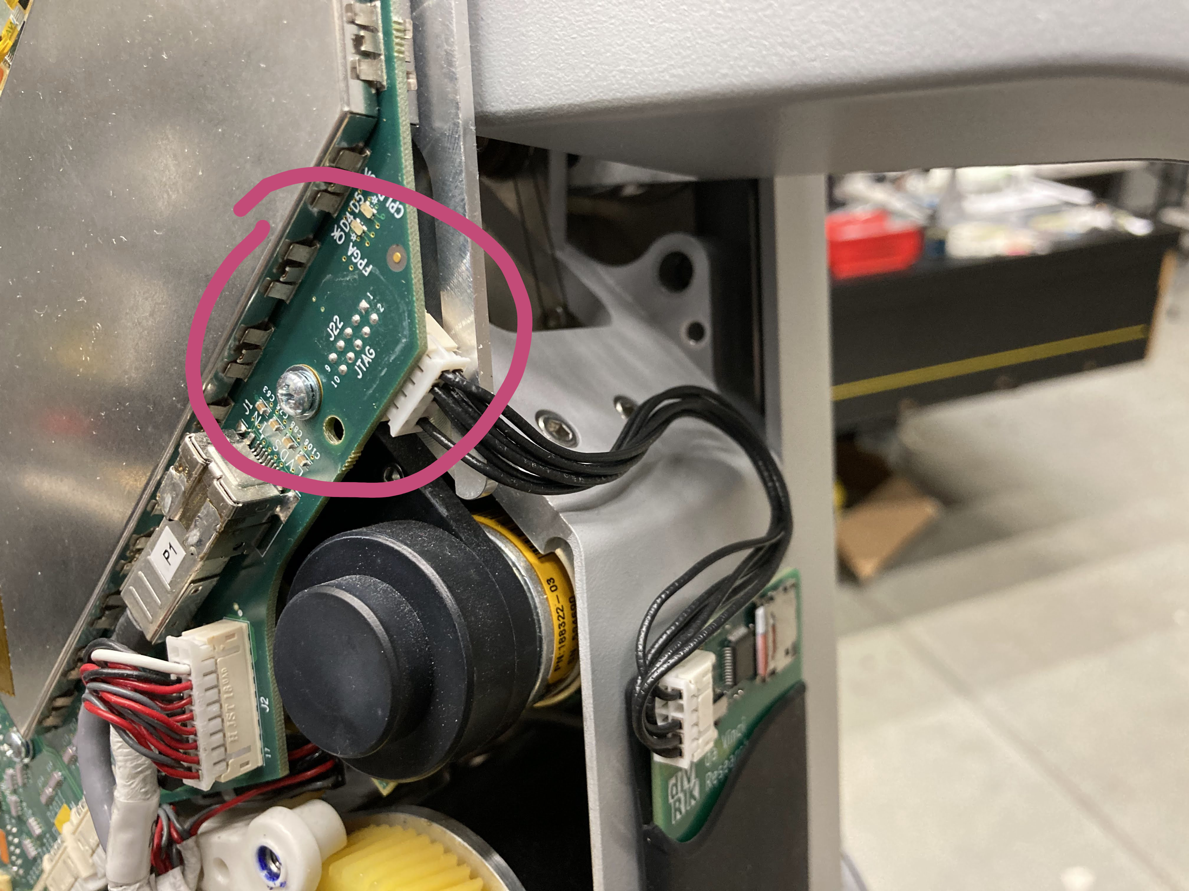
ESPM JTAG and ESPM programmer
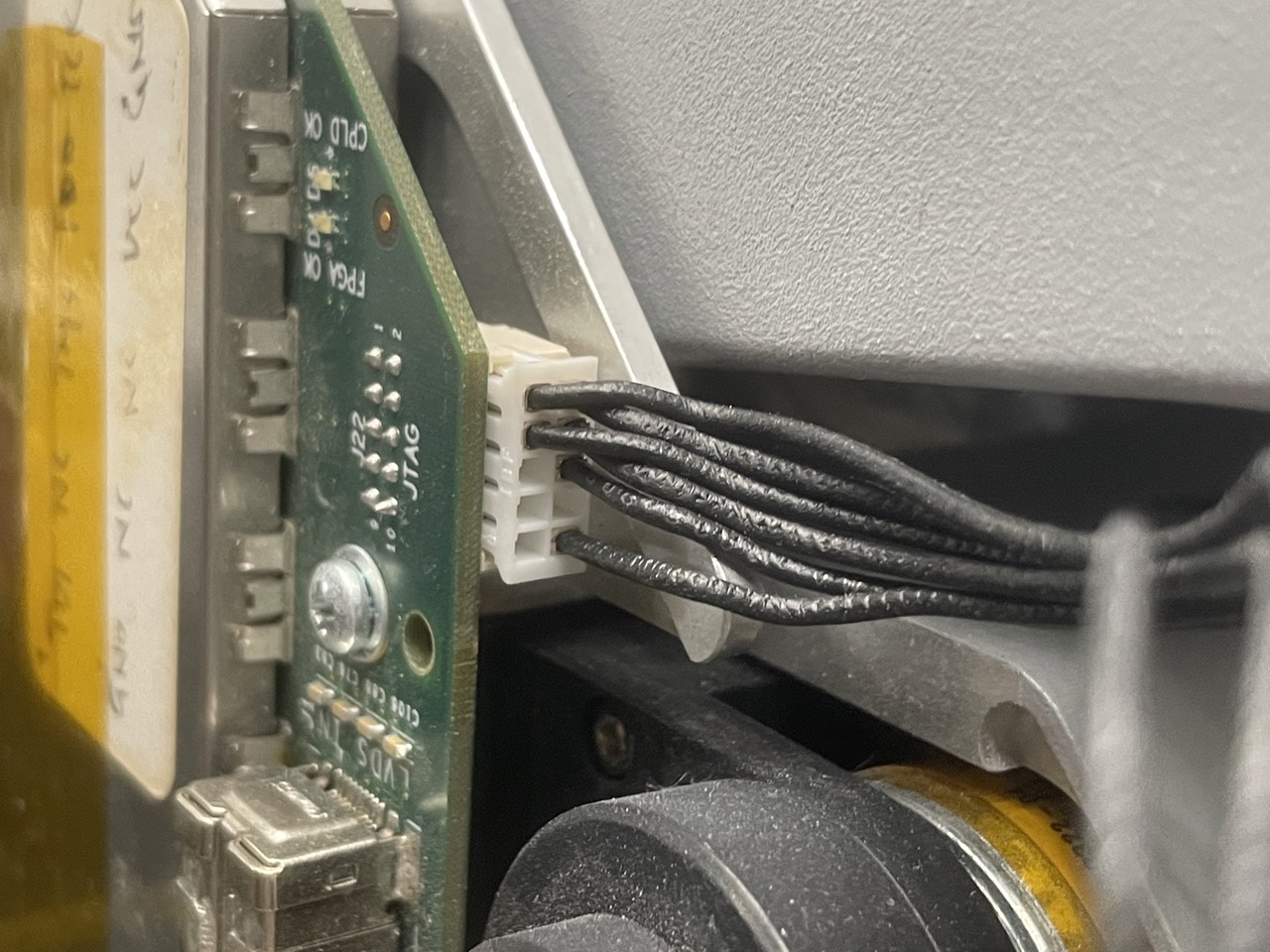
ESPM programmer connected to ESPM JTAG
To hold the ESPM programmer to the arm, you should have received a rubber credit card holder with double-sided tape. Place the ESPM programmer in the holder, then stick the holder on the robot as shown below. Put the plastic cover back on the arm while making sure the cover is not pinching the cable.

ESPM programmer on arm
Note
If the arm is folded, and you can’t access the surface to stick the holder, you can let it hang until you can power the arm and release the brakes. Alternatively, you can force the arm to move despite the brakes. This is not something you should do too often, but it can help during the setup: YouTube video.
3.4.3.3. Usage
Make sure that the switch on the ESPM programmer is set to “enable”, and that the micro SD card is present.
3.4.3.4. Troubleshooting
The blue or white LED indicates normal operation. After powering up, expect the blue or white light to flash rapidly (may appear dimly lit) for a couple seconds, followed by solid on for 2 seconds, then off.
On error, you will see blinking yellow LED. Count the number of blinks between the 2-second intervals:
2: SD card hardware or filesystem problem
   /* Try re-inserting the card. Then try formatting and re-flashing the card. */
3: Can't find/open espm.xsvf
   /* Try re-flashing the card. */
4: XSVF_ERROR_UNKNOWN
5: XSVF_ERROR_TDOMISMATCH
6: XSVF_ERROR_MAXRETRIES
7: XSVF_ERROR_ILLEGALCMD
8: XSVF_ERROR_ILLEGALSTATE
9: XSVF_ERROR_DATAOVERFLOW
The most common user errors are 2 and 3. Other errors indicate problems with the firmware image. The firmware flashing is completely open loop. A successful firmware flash reported by ESPM Programmer (blue/white light for 2 seconds) does not indicate a working ESPM.